Download
1 / 27
270 likes | 456 Views
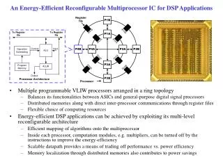
An Efficient Asymmetric Distributed Lock for Embedded Multiprocessor Systems. 黃 翔 Dept. of Electrical Engineering National Cheng Kung University Tainan, Taiwan, R.O.C 2013.03.24. Abstract . Efficient synchronization is a key concern in an embedded many-core system-on-chip ( SoC ).

E N D
An Efficient Asymmetric Distributed Lock for Embedded Multiprocessor Systems 黃 翔 Dept. of Electrical Engineering National Cheng Kung University Tainan, Taiwan, R.O.C 2013.03.24
Abstract • Efficient synchronization is a key concern in an embedded many-core system-on-chip (SoC). • The use of atomic read-modify-write (RMW)instructions combined with cache coherency as synchronization primitive is not always an option for shared-memory SoCsdue to the lack of suitable IP. • This paper introduces an asymmetric distributed lock algorithm for shared-memory embedded multiprocessor systems without hardware cache coherency. • Messages are exchanged via a low-cost inter-processor communication ring in combination with a small local memory per processor.
1.Introduction (1/2) • In modern general purpose chips, synchronization is usually polling-basedusing atomic read-modify-write (RMW) operations. • RMW operations have a relatively low latency and are wait-free. • However, they require a cache coherent system, which is hard to realize in general and absent in Intel’s 48-core SCC. • Without cache coherency, RMW operations induce traffic to external SDRAM, which has a limited bandwidth and high latency. • Hardware cache coherency or RMW instructions are not always applied in embedded systems, because of high hardware costsand the lack of IP. • The alternative is to use a generic software implementation of a synchronization algorithm, like the bakery algorithm for mutexes.
1.Introduction (2/2) • Again, the SDRAM is then used for synchronization, which is a scarce resource, as a single bank is shared among many cores. • The memory can be bypassed for synchronization completely when using a distributed lock via message-passing,which requires local memoriesand aninter-processor network. • We evaluate a 32-core SoCarchitecture and show that adding alow-cost inter-processor communication ring for synchronization reduces the required SDRAM memory bandwidth. • An efficient distributed lock algorithm is presented that reduces the average latency of locking, by exploiting the locality of mutexes.
3.Platform: 32-Core SoC (1/6) • We designed and built a 32-core many-core SoC to make realistic observations and run solid experiments. • The SoC is based on MicroBlaze tiles, as depicted in Figure 1. Fig.1: MicroBlaze tile
3.Platform: 32-Core SoC (2/6) • This section is classified into four parts : A. Tiles and Memory Hierarchy B. Tree-shaped Interconnect with FCFS C. Synthesis for FPGA D. Software: Kernel and Applications
3.Platform: 32-Core SoC (3/6) A. Tiles and Memory Hierarchy • Such tile contains the MicroBlaze core, a local memory that is used to boot from and store a few local variables of the kernel, and a PLB bus. • To this bus, a timer is connected, which is the only interrupt source of the MicroBlaze. • The MicroBlaze has a 16 KB instruction cache and 8 KB data cache - both connected to the local PLB bus. • All code resides in main memory. • The stack and heap of the core also reside in main memory and are cached. • Since the MicroBlaze has no hardware cache coherency, inter-processor communication is done via a part of the main memory that is uncached.
3.Platform: 32-Core SoC (4/6) A. Tiles and Memory Hierarchy • The 256 MB main memory is accessible via an interconnect (see Figure 2(a)), which is quite expensive in terms of latency input packets timestamp added FCF arbitration: binary tree serialized packets (a) System structure (b) Arbitration tree structure Fig. 2: Structure of the system
3.Platform: 32-Core SoC (5/6) B. Tree-shaped Interconnect with FCFS • Figure 2(b) shows the structure of the interconnect, which is a packet switched network-on-chip, with its main purpose to gain access to the main memory. • The interconnect arbitrates requests of all 32 cores to a bus, where a memory controller and peripherals are connected to. • Every single request is separately packetized, containing one command, one address, and multiple data flits. • The packet will receive a timestamp for first-come-first-served (FCFS) - arbitration and a processor ID upon injection, which is sent along with the packet. • The response of requests will be sent back via a similar tree, which routes the packet based on the processor ID, without the need of arbitration.
3.Platform: 32-Core SoC (6/6) D. Software: Kernel and Applications • The kernel can run multiple processes in a multi-threaded fashion, without process migration between kernels. • From a kernel point of view, daemons, servers, and (worker) threads from applications are just processes. • MicroBlazescan only communicate via main memory, and no RMW instructions are available. • Table I lists all applications used for the experiments. TABLE I: APPLICATIONS
4.Memory and Mutex Profile (1/4) • The memory controller has hardware support to measure memory traffic. • Using this information and profiling data measured by the MicroBlaze and operating system, traffic streams of the applications can be identified, which is plotted in Figure 3. Fig. 3: Measured traffic on SDRAM controller (a) by processing time (b) by memory bandwidth
4.Memory and Mutex Profile (2/4) • Figure 3(a) depicts on which operations the time is spent by the memory controller. • The bandwidth usage corresponding to Figure 3(a) is shown in Figure 3(b). • Although the controller is saturated for all applications, the bandwidth greatly differs, because word reads/writes take almost the same amount of time as burst reads/writes, but leave most of the potential bandwidth unused. • Mutex operations contribute by 35% on average to the memory controller load and 18% to the bandwidth usage.
4.Memory and Mutex Profile (3/4) • Figure 4 shows additional information about the state of the mutexes of the same applications. • The hatched area shows the fraction of mutexes that where not only free, but also classified as relocks: A successive lock on the same mutex by the same process. Fig. 4: Mutex locking behavior per application
4.Memory and Mutex Profile (4/4) • Based on Figure 4, it can be concluded that most of the mutexesare usually free and reused by the same process, so a mutexis (mostly) local. • Since mutexes only require a small amount of memory, they can be kept locally, in a (noncoherent) cache.
5.Ring and Distributed Lock (1/6) • In order to implement inter-processor communication to bypass main memory, the architecture is extended with an additional interconnect: a ring topology, which is depicted in Figure 5. • The ring allows write-only access to the local memory of all other MicroBlazes, where a MicroBlaze can read and write its own local memory. Fig. 5: MicroBlaze tile with additional ring
5.Ring and Distributed Lock (2/6) • The network can be kept low-cost, because 1) the required bandwidth for the synchronization is low 2) the routing in a ring is trivial, and thus cheap 3) the latency of one clock cycle per tile is not an issue, because most of the latency is introduced by the software of the message handling daemons - even when 100 cores are added, the increased latency by the ring is much less than a single context switch to the daemon. • Inter-process messages are sent and received via a message handling process (one per MicroBlaze) that schedules outgoing messages and dispatches incoming messages to the appropriate local process. • All messages are processed sequentially by this daemon in FCFS manner.
5.Ring and Distributed Lock (3/6) • Based on message-passing, a new asymmetric distributed lock has been designed, where ‘asymmetric’ points to the different roles of participants in the algorithm. • The main idea is that when a process wants to enter a critical section - and tries to lock a mutex - it sends a request to a server. • This server either responds with “You got the lock and you own it”, or “Process n owns the lock, ask there again”. • In the latter case, the locking process sends a message to n, which can reply with “The lock is free, now you own it”, or “It has been locked, I’ll signal you when it is unlocked”. • When a process unlocks a lock, it will migrate it to the process that asked for it, or flag it is being free in the local administration otherwise. • In this way, processes build a fair, distributed, FCFS waiting queue.
5.Ring and Distributed Lock (4/6) • Algorithms 1 to 3 show the implementation. • lock server (Algorithm 1): a process that registers the owner process of a lock using the map M. Algorithm 1 Lock server Global: M : lock → process, M ← Ø Procedure: request(l ; r) Input: process r requesting lock l 1: ifM(l) is undefined then 2: M(l) ← r 3: return got lock l 4: else 5: p ← M(l) 6: M(l) ← r 7: return ask p for state of l Procedure: giveup(l; r) Input: process r giving up lock l 8: ifM(l) = rthen 9: undefineM(l)
5.Ring and Distributed Lock (5/6) • message handler (Algorithm 2): every MicroBlazeruns a single message handling daemon, which handles incoming message. Algorithm 2 Message handling daemon Global: administration of owned locks of local process p: Lp: lock → { free, locked , migrate , stolen}, ˅p : Lp← Ø Procedure: ask(l; p; r) Input: lock l, owned by process p, requested by r 1: atomic 2: ifLp(l) is undefined then 3: return free 4: else if Lp(l) = locked then 5: Lp(l) ← migrate on unlock to r 6: return locked 7: else 8: Lp(l) ← stolen 9: return free
5.Ring and Distributed Lock (6/6) • locking process (Algorithm 3): the process that wants to enter a critical section. Algorithm 3 Locking process Global: Lself , which is one of Lp of Algorithm 2 Procedure: lock(l) Input: lock l 1: atomic 2: s ← Lself (l) 3: Lself(l) ← locked 4: if s ≠ free then 5: if request(l,self) = ask pthen 6: if ask(l,p,self) = locked then 7: wait for signal (signal counterpart at line 14) Procedure: unlock(l) Input: locked lock l 8: dummy read SDRAM 9: atomic 10: s Lself (l) 11: Lself (l)free 12: if s = migrate to rthen 13: undefineLself (l) 14: signal r (wait counterpart at line 7) 15: elseif too many free locks in Lselfthen 16: l’ ← oldest free lock in Lself 17: undefineLself (l’) 18: giveup(l’,self)
6.Bakery vs. Distributed Lock (1/6) • To evaluate the distributed lock, experiments are conducted on two systems: the bakery implementation in the architecture without ring, referred to as the base case; and the distributed lock via the ring. A. Result • Figure 6 shows the types of memory traffic of both the base case and the distributed lock. • In Table II, the measured number of exchanged messages is depicted. • Performance numbers, which are averaged over all runs, of the applications are shown in Figure 7. • All values are normalized to the base case, which is 1 by definition. • Although the different concepts of a lock server and message handling daemon are important in the algorithm, the functionality of the server is merged into the daemon in the actual implementation. • This allows a quick response of request and give up messages.
6.Bakery vs. Distributed Lock (2/6) Fig. 6: Measured traffic on SDRAM controller, using bakery and distributed locks
6.Bakery vs. Distributed Lock (3/6) a See Algorithms 1 to 3 b Lock messages exchanged per second over the ring TABLE II: DISTRIBUTED LOCK STATISTICS
6.Bakery vs. Distributed Lock (4/6) Fig. 7: Difference between using bakery algorithm and asymmetric distributed lock with ring
6.Bakery vs. Distributed Lock (5/6) B. Discussion • There is a trade-off between a main memory polling algorithm like bakery that consumes scarce bandwidth, or keeping (or caching) mutexes locally and having higher latencies for non-local mutexes. • Figure 8 gives insight into this trade-off. Fig. 8: Impact of locality on acquiring time of a mutex lock, based on synthetic benchmark
6.Bakery vs. Distributed Lock (6/6) B. Discussion • Naturally, when a mutex is used by only one process, it is always local and locking it is very fast. When mutexesare used by more processes, the lock must be migrated regularly, which involves communication between cores. • Hence, the amount of expensive communication depends on the locality of the mutex, which we define as the fraction of relocks over free locks. • For the four applications, the locality is respectively 0.91, 0.71, 0.95, 0.66. • This shows that applications with globally used mutexes, possibly do not benefit from the distributed lock, but the tested applications are all at the right side of the break-even point. • Calculations indicate that the applications still spent respectively 35%, 26%, 0.2% and 9.2% of the execution time on mutexlocking operations. Additionally, during this locking time, 77%, 95%, 85% and 95% of the time is spent waiting for locked mutexes. • Hence, improving the locking speed any further will hardly lead to a performance increase; making locks more local is probably more beneficial.
7. Conclusion • This paper presents an asymmetric distributed lock algorithm for non-cache coherent embedded multiprocessor systems. • In our solution, mutex related SDRAM memory traffic is completely eliminated and replaced by synchronization messages via a low-cost write-only ring interconnect. • Measurements indicate that of all tested applications, the locality of mutexes is high. • Our asymmetric lock benefits from this locality. • Additionally, these experiments show that although any-to-any communication can be realized via main memory, the addition of a low-cost ring is beneficial, even when it is only used for synchronization.