Download
1 / 70
700 likes | 733 Views
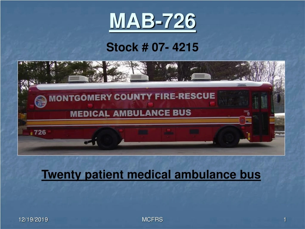
MAB-726. Stock # 07- 4215. Twenty patient medical ambulance bus. MAB-726. Specifications. Bus length: 37 feet Bus exterior width: 96 inches Interior width: 90 inches Bus exterior height: 12 foot 4 inches

E N D
MAB-726 Stock # 07- 4215 Twenty patient medical ambulance bus MCFRS
MAB-726 Specifications • Bus length: 37 feet • Bus exterior width: 96 inches • Interior width: 90 inches • Bus exterior height: 12 foot 4 inches • Interior height: 78 inches • Engine: C-7 Caterpillar 230 horsepower • Transmission: Allison 3000 PTS/Trans Synd • Alternator: Leece Neville 270 amp • Generator: 12 KW Martin diesel generator • Oxygen system: 2 banks, 4 K bottles per bank MCFRS
MAB-726 Specifications TIRES Front Size: 275/70R22.5 Pressure: 125psi Rear Size: 255/70R22.5 Pressure: 120psi Fluids Transmission : Trans-Synd Engine oil: 15W40 CJ4 Engine Coolant: Alliance 50/50 mix recommended Power steering: Dexron III MCFRS
MAB-726 Engine compartment checkout • Unless the 10 bolts are removed from the floor the engine check is very limited. • On a creeper inspect the condition of belts and hoses from the underside of the engine. • Check for fluid leaks. MCFRS
Power steering dipstick Engine oil dipstick Power steering fill Oil fill Transmission fill and dipstick MAB-726 Engine compartment checkout Engine oil is 15-40 weight CJ4 Power steering fluid is dexron III Transmission fluid is Trans-Synd MCFRS
MAB-726 Transmission fluid check Keypad transmission fluid check • There is no need to pull the transmission dipstick to check the fluid level. • Transmission must be at 150 degrees and at idle for five minutes on level ground. • Push the up and down arrow at the same time once. • Key pad will display “OL” “HI or LO” 1 thru 7.This is the number of quarts low or high. • Push N to return to normal mode. MCFRS
MAB-726 Engine compartment checkout Front panels Panel latches MCFRS
Electrical switches Windshield washer reservoir Radiator Reservoir Air filter restriction indicator Radiator overflow can MAB-726 Center and left panel Center panel Drivers left panel MCFRS
MAB-726 Electrical resets • These switches are located in the drivers left front panel. • If power is lost either to the 12 volt body or chassis components cycle these switches. Left panel MCFRS
Circuit breakers Fuse panel MAB-726 Drivers side electrical compartment Circuit breaker covers This panel is located under the drivers window. Plastic covers are held in place by door pressure MCFRS
MAB-726 Battery compartment Locked position Unlocked position 3 group 31 batteries on a sliding tray located on the drivers side. MCFRS
On Off MAB-726 Door operation After turning the batteries on you must return this lever to the normal position for the doors to shut. After turning the batteries off you must place this lever in the emergency position and push the doors open. Master battery switch MCFRS
MAB-726 Door operation • After the batteries have been turned on, and the emergency door lever has been returned to the normal position, use this switch to control the door. MCFRS
MAB-726 Emergency door operation Emergency This panel is located to the left of the front door. If the bus is running and the doors are shut. Place the lever in the emergency mode and pull doors open. Normal MCFRS
MAB-726 Drivers controls This panel controls 12 volt dome lights, wiper controls, and mirror heat. This auxiliary power port is located to the rear of the switch panel MCFRS
MAB-726 Mirror controls Mirror controls These switches are located by the drivers left knee. MCFRS
MAB-726 Mirror controls Place white dot on respective arrow to control the mirror Mirrors are adjusted up, down, left, and right by the center knob MCFRS
MAB-726 Steering wheel adjustment • This lever is on the left side of the steering column. • It is below the turn signal • Pull the lever for steering wheel tilt. • Push lever for extension and retraction MCFRS
MAB-726 Drivers seat controls Adjusting screw The gray button is for lumbar support The red button is for seat up and down To adjust armrest turn the adjusting screw in the appropriate direction for up and down. MCFRS
MAB-726 Drivers seat • If seat will not adjust by air, pull up the seat cushion from the rear and check the air lines. MCFRS
MAB-726 Air gauge • This single air gauge has dual needles. • The green needle is for the primary system. (Rear brakes) • The orange needle is for the secondary system. (Front brakes) • Doors and accessories will not work until air pressure has reached 85 psi Location is lower left side of dash MCFRS
MAB-726 Cruise control and fast idle switches • To set the cruise control place the cruise switch to the on position. • At desired speed push the set button. • Fast idle switch is a momentary switch. • Use the fast idle switch when at idle for long periods of time. Location is lower left side of dash MCFRS
MAB-726 Heater and defroster controls • This panel is located at the mid dash area. • The left switch is for defroster and right switch is for the right heater. MCFRS
Safety cover Warning light MAB-726 Rear suspension air dump • This switch will lower the rear of the bus approximately four to six inches to ease in the loading of patients. • Activate switch by raising the safety cover and toggle the switch. • The red indicator light will illuminate. Air is now exhausting the air bags. MCFRS
Activated position MAB-726 Rear suspension air dump • The air bags will deflate allowing the body to rest on the axle stops. • You must place switch back into the normal position before moving the bus. • There are no interlocks preventing movement of the bus when the switch is activated. MCFRS
Power switch 3 position emergency light switch Siren control MAB-726 Emergency lights and siren control • All the emergency lights and the siren are controlled thru this unit. • For emergency lights push the lever to the left. • 1st position is green for rear lights • 2nd position is yellow for side lights and rear lights. • 3rd position is red for all emergency lights. MCFRS
MAB-726 Generator system • This is a Martin 12,500 watt continuous use diesel generator. • It will supply all AC/heater units plus all interior lights and oxygen system, with approximately 2000 watts remaining for use. • Limit exterior use to 500 watts per outlet. Oil is 15W40 CJ4 71/2 quarts Antifreeze is 50/50 mix 2 gal. MCFRS
Radiator overflow Oil fill Oil dipstick Oil Drain MAB-726 Generator system MCFRS
MAB-726 Generator system • This is the Fuel /water separator. • Make sure valve is in this position, always check after servicing. • If the valve is not in this position the generator will not run. Open position MCFRS
Air filter restriction gauge MAB-726 Generator system • When the air cleaner becomes restricted a yellow flag will be drawn up into the clear window. • When this yellow flag is visible half way through the window. The air cleaner must be serviced. MCFRS
MAB-726 Generator system • To start the generator make sure the bus is running. • In temperatures of 40 degrees or lower hold the glow plug switch down for 15 seconds. • Push the start toggle upwards and hold until the green indicator illuminates. • Always start the generator with the bus engine running Indicator light MCFRS
MAB-726 Generator system • This is the master panel for the generator and it will display why the generator shut down. • Oil pressure below7psi will shut the generator down. • Water temperature above230 degree will shut the generator down. MCFRS
Toggle this switch upwards if generator fails to crank. MAB-726 Generator system • These switches are on the right side of the panel box. • If starting the generator and it quickly stops and will not crank you must reset fuel prime/glow switch. • The generator can be started and stopped from this switch MCFRS
MAB-726 Generator system • This is the main breaker to the circuit box. • If there is no 120 volt electrical power at any point check this breaker MCFRS
Air bag fill MAB-726 Generator system • The generator rests on four air bags • These air bags allow the generator to flex on the bags. • Both front air bags have the air fill for the front and rear bag on that side. • Remove the cap and add air in small amounts MCFRS
Sliding tray release MAB-726 Generator system • The generator is on a sliding tray for ease in maintenance. • Pull the release upwards and pull the tray outward. • If the generator radiator tunnel drags on the compartment, air needs to be added to the air bags. MCFRS
Sliding tray release and lock MAB-726 Generator system • When sliding the tray back in make sure that the lock engages and tray is secure. • There are no interlocks or warning devices if the tray is not secure. • Movement of the bus without the sliding tray secure will result in damage. MCFRS
Panel is showing shoreline power. MAB-726 Manual electrical transfer switch Located inside of bus on curb side wall • This is the manual transfer panel that determines if you are on generator power or shoreline power. • Push the circuit breaker towards the center of the box for appropriate setting. • You cannot use generator and shoreline power at the same time. MCFRS
MAB-726 120/240 volt shoreline • This is the 120/240 volt, 50 amp. electrical shoreline. • It is the white box located by the entrance door. • If on a 15 amp circuit you can use one AC/heater unit and all interior lights. • On a 20 amp circuit you can use two AC/heater units and all interior lights. • You need at least a 30 amp circuit to use all three AC/heater units. This connection is located by main entrance door MCFRS
50 amp circuit Battery conditioner MAB-726 Battery conditioner (charger) • When the MAB is being used as a platform you will be using the 50 amp electrical shoreline circuit. • You must also use the battery conditioner (charger) line to maintain the 12 volt system. MCFRS
MAB-726 Battery conditioner (charger) • If only the 120/240 volt line can be used from the electrical source you can do the following. • Use the 120 volt outlet by the door and connect back into the battery conditioner. • This jumper cord is attached to the 50 amp shoreline. Battery conditioner 120 volt outlet MCFRS
MAB-726 Main electrical circuit box Located inside of bus on curb side wall • This is the main electrical panel and is located on the passenger side of the bus. • All 120 volt circuits are controlled thru this panel. • All O2 circuits are thru this panel also. MCFRS
Drivers side Passenger side MAB-726 GFI electrical outlets • All 120 volt outlets are GFI protected. • The drivers side outlets are protected by the GFI plug located at the O2 station. • The passenger side GFI outlet is located between the O2 shutoff and the main electrical box. It is the left outlet. MCFRS
MAB-726 GFI electrical outlet • If power is lost to one side of the GFI outlets you must reset the appropriate GFI outlet. • If still no power you must go back to the main electrical box and reset the breaker. • If all 120 volt power is out you must go to the main breaker on the generator. • When outlets are tripped the light in the GFI outlet will illuminate . • Push the lower button to reset. Light Reset MCFRS
MAB-726 Oxygen system • The oxygen system consists of two banks of four “K” bottles. • There are two bottles per slide out tray. • Between the two banks is the computer which determines which bank is the primary and secondary. • Inside the bus is the main shutoff and the monitoring station. MCFRS
MAB-726 Oxygen system • When oxygen use is required open all bottles on both banks. • You need not slide the trays out. WARNING • Open bottles slowly due to the length of the piping. This will prevent the possibility of a flash fire. MCFRS
MAB-726 Oxygen distribution system • After all of the bottles are open oxygen flows to the computer controlled distribution box. • This control box will automatically handle which bank will be the primary and secondary system. • It also has the ability to distinguish liquid oxygen from gas. MCFRS
MAB-726 Oxygen distribution system • This box will display which bank is in primary mode and the other in secondary. • The display screen will show delivery pressure, left and right bank pressure. • This switch controls what is displayed on the display screen. Left for left bank, right for right bank, and delivery pressure. MCFRS
Primary Secondary MAB-726 Oxygen distribution system • This photo shows the left bank as the primary system. (Green light) • The right bank is in the secondary mode or standby mode. (Amber light) • The screen is displaying the delivery pressure. MCFRS
MAB-726 Oxygen distribution system • When the oxygen is required these switches should be these positions. • Pressure Display Select • Switch will be in the center position. (Delivery) • Inlet Gas Priority Select • Switch to be in center position. (FIFO) • Switchover Pressure Select • Switch to be in the off position MCFRS


![C8010-726 Exam Dumps - Actual C8010-726 Dumps PDF [2018]](https://cdn4.slideserve.com/7926564/slide1-dt.jpg)