Download
1 / 26
270 likes | 403 Views
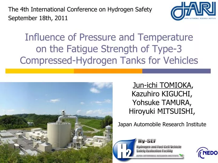
The 4th International Conference on Hydrogen Safety September 18th, 2011. Influence of Pressure and Temperature on the Fatigue Strength of Type-3 Compressed-Hydrogen Tanks for Vehicles. Jun-ichi TOMIOKA , Kazuhiro KIGUCHI, Yohsuke TAMURA, Hiroyuki MITSUISHI ,

E N D
The 4th International Conference on Hydrogen Safety September 18th, 2011 Influence of Pressure and Temperature on the Fatigue Strength of Type-3 Compressed-Hydrogen Tanks for Vehicles Jun-ichi TOMIOKA, Kazuhiro KIGUCHI,Yohsuke TAMURA, Hiroyuki MITSUISHI, Japan Automobile Research Institute
Background 1 – Hydrogen Tank 35MPaType-3 Aluminum Alloy Liner “Fuel Cell” or “Hydrogen Engine” Carbon Fiber Reinforced Plastic (CFRP) 35 MPa Compressed Hydrogen Tanks Type-3 : Fully wrapped composite tanks with metal liners Type-4 : Fully wrapped composite tanks with plasticliners www.peugeot.com
Pressure Time Background 2 – Fatigue Strength • Fatigue strength against pressure cycling. • Hydraulic pressure cycle test • examination of fatigue life • fluid temperature changes slightly • 300 cycles per one hour • Gas cycle test • examination of fatigue life and hydrogen embrittlement • gas temperature changes greatly • 1 cycle per one hour Leak... It is not clear what effect the diferences in the test methods have on the fatigue process.
Background 3 – Load on Tank 35MPa Type-3 Aluminum Alloy Liner thermal expansion: large • Internal pressure (gas) • Pressure changes with temperature, even if the same mass is filled. • SOC (State of charge) :hydrogen-filled state based on hydrogen-mass in the tank. • Thermal stress • Because of differences in thermal expansion rates, thermal stress is generated by temperature changes. CFRP thermal expansion: small Fatigue life under the SOC100% condition is not clear
Purpose • To clarify the influence of environmental temperature and pressure assuming SOC100% on the fatigue life of compressed hydrogen tanks for vehicles. • Hydraulic pressure cycle tests with varying environmental temperatures and pressures • LT(low temp.) : -40°C, 28MPa • RT(room temp.) : 15°C, 35MPa • HT(high temp.) : 85°C, 44MPa • AT(ambient temp.) : 15°C ~25°C, 44MPa
Carbon Fiber Reinforced Plastic (CFRP) Layer Liner DomeSection Tail End Plug Cylindrical Section Specification of Test Tank Specification of Test Tank Schematic Diagram of Compressed Hydrogen Tank
Test Equipment – Hydraulic Tester hydraulic Tester High pressure pipe Thermostatic Chamber Intensifier Pump Power Unit Thermostatic Chamber 120 MPa Intensifier Constant-temperature (-40 ~ 150 deg.C)
Test Conditions Test conditions of pressure cycle test Pressure profile of cycle test * Ambient-Temperature Pressure-Cycle Test specified in JARI S001
Fatigue Life of Type-3 Tank the mean ± S.E., N=2 SOC100% SOC125% Leak Leak Leak Leak Fatigue life determined by hydraulic pressure-cycle tests • Leakage occurred in all tanks • Lives under SOC 100% were longer than the life under AT(SOC125%). • →Pressure-cycle test under AT(SOC125%) can ensure the safety of a Type-3 tank against fatigue.
Liner Stress of Type-3 tank • ①Stress due to internal pressure • (tensile stress) • ②Residual stress • Autofrettage processing produces residual stress (CFRP: tensile stress, Liner: compressive stress) • ③Thermal stress • Because of differences in thermal expansion rates in aluminum alloy and CFRP To determine the liner stress, we measured the strain on the inner surface of the liner.
①Stress due to Internal Pressure Strain gauge on the liner Hydraulic pressure Hydraulic system Measuring method for strain due to internal pressure • Strain gauges were attached to the inner surface of the liner • Applying pressure to the tank • Measuring the strain due to internal pressure • Caluculate the stress based on the measured strain. The inner surface of the liner
①Stress due to Internal Pressure Relationship between pressure and stress of the liner • Relationship between pressure and stress of the liner was linear-proportion.
②Residual Stress Cut1 Cut 3 : Separate CFRP and Liner Cut2 a A a A CFRP Liner B b B b Strain gauges Strain gauges A, B : Outer surface of CFRP a, b : Inner surface of liner Measuring method for residual strain • In all tanks after the pressure-cycle test, strain gauges attached to the outer surface of the CFRP and the inner surface of the liner • Cutting the tank at room temperature (15°C) to release the residual strain • Measuring the residual strain • Caluculate the stress based on the measured strain.
②Residual Stress (Measured results) Residual strain of the tank after the pressure-cycle test at RT • Tensile strain resided in the CFRP and compressive stress resided in the liner. Residual stress of Liner • Residual stress of the liner after pressure-cycle test at HT was smallerthan the others.
③Thermal Stress Thermostatic Chamber -40°C~85°C Thermocouple Thermocouple ε1 ε2 Strain gauge Aluminum tube Strain gauge εts: Strain due to the thermal stress ε1: Strain of the liner ε2: Strain of the aluminum tube εts = ε1 - ε2 Measuring method for thermal strain • Strain gauges and thermocouples were attached to the inner surface of the liner and the aluminum tube • Changes in the temperature ranging from -40°C to +85°C(①15°C→②-40°C→③15°C→④85°C→⑤15°C) • Measuring the thermal strain • Caluculate the stress based on the measured strain.
③Thermal Stress plastic deformation (yield stress: 300MPa) Relationship between temperature and circumferential stress of the liner • In high-temperature and low-pressure, the liner was loaded with residual compressive stress and compressive stress due to the thermal stress. • →The liner was deforemd plastically in high-temperature and low-pressure.
Liner Stress (hydraulic cycle) AT ( 15~25°C, 44MPa) LT -40°C, 28MPa RT 15°C, 35MPa HT 85°C, 44MPa plastic deformation (yield stress: 300MPa) Relationship between temperature and circumferential stress of the liner • Tensile stress at AT (SOC125%) exceeds that under any SOC100% condition. • ⇒The pressure-cycle test underAT can ensure the safety of a Type-3 tank against fatigue life.
Liner Stress (gas cycle) gas cycle at -40°C gas cycle at 15°C Relationship between temperature and circumferential stress of the liner • the gas cycle is the repetition of a low-temperature and low-pressure condition and a high-temperature and high-pressure condition. • →The liner will be not deforemd plastically in gas cycle.
Liner Stress (hydraulic and gas) gas cycle at -40°C LT -40°C RT 15°C HT 85°C gas cycle at 15°C Relationship between temperature and circumferential stress of the liner • The stress range during gas cycles is smaller than during hydraulic cycles. • ⇒Hydraulic cycles are more severe than gas cycles.
Summary • Pressure cycle tests assuming SOC 100% in type-3 tanks revealed that • The fatigue life assuming SOC 100% is longer than the room temp. pressure cycle test (AT,SOC125%). • The room temp. pressure cycle test (AT,SOC125%) can ensure the safety of a Type-3 tank against fatigue. • Stress range during gas cycles is smaller than during hydraulic cycles, so the hydraulic-cycle tests are more severe than gas-cycle tests.
Thank you This study is summarizes part of the results of "Establishment of Codes & Standards for Hydrogen Economy Society - Research and Development Concerning Standardization of Hydrogen and Fuel Cell Vehicles" consigned by the New Energy and Industrial Technology Development Organization (NEDO).