Download
1 / 45
450 likes | 669 Views
EECS 373 Design of Microprocessor-Based Systems Prabal Dutta University of Michigan Lecture 11: Sampling, ADCs, and DACs Oct 12, 2010 Slides adapted from Jonathan Hui http://www.cs.berkeley.edu/~jwhui. Announcements. Homework, Labs, and Minute Quizzes Office Hours

E N D
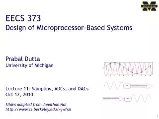
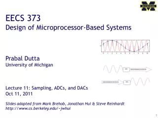
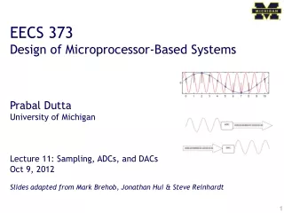
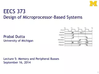
EECS 373 Design of Microprocessor-Based Systems Prabal Dutta University of Michigan Lecture 11: Sampling, ADCs, and DACs Oct 12, 2010 Slides adapted from Jonathan Hui http://www.cs.berkeley.edu/~jwhui
Announcements • Homework, Labs, and Minute Quizzes • Office Hours • Tuesday, Oct 12, 2:30 PM – 3:30 PM, in EECS 2334 • Thursday, Oct 14, 1:30 PM – 3:00 PM, in CSE 4773 • Last ones before the midterm • Midterm • Thursday, Oct 21, 2010 • 10:40 AM – 11:30 AM (50 minutes) • In-class • Labs
Outline • Minute quiz • Announcements • Sampling • ADC • DAC
We live in an analog world • Everything in the physical world is an analog signal • Sound, light, temperature, pressure • Need to convert into electrical signals • Transducers: converts one type of energy to another • Electro-mechanical, Photonic, Electrical, … • Examples • Microphone/speaker • Thermocouples • Accelerometers
Transducers convert one form of energy into another • Transducers • Allow us to convert physical phenomena to a voltage potential in a well-defined way.
Convert light to voltage with a CdS photocell Vsignal = (+5V) RR/(R + RR) • Choose R=RR at median of intended range • Cadmium Sulfide (CdS) • Cheap, low current • tRC = Cl*(R+RR) • Typically R~50-200kW • C~20pF • So, tRC~20-80uS • fRC ~ 10-50kHz Source: Forrest Brewer
Force strain gauges - foil, conductive ink conductive rubber rheostatic fluids Piezorestive (needs bridge) piezoelectric films capacitive force Charge source Sound Microphones Both current and charge versions Sonar Usually Piezoelectric Position microswitches shaft encoders gyros Acceleration MEMS Pendulum Monitoring Battery-level voltage Motor current Stall/velocity Temperature Voltage/Current Source Field Antenna Magnetic Hall effect Flux Gate Location Permittivity Dielectric Many other common sensors (some digital) Source: Forrest Brewer
Engineering Units Physical Phenomena Voltage or Current ADC Counts Sensor ADC Software Going from analog to digital • What we want • How we have to get there Physical Phenomena Engineering Units
Representing an analog signal digitally • How do we represent an analog signal? • As a time series of discrete values On MCU: read the ADC data register periodically V Counts
Range Too Big Range Too Small Ideal Range Choosing the horizontal range • What do the sample values represent? • Some fraction within the range of values What range to use?
Choosing the horizontal granularity • Resolution • Number of discrete values that represent a range of analog values • MSP430: 12-bit ADC • 4096 values • Range / 4096 = Step Larger range less information • Quantization Error • How far off discrete value is from actual • ½ LSB Range / 8192 Larger range larger error
Converting between voltages, ADC counts, and engineering units • Converting: ADC counts Voltage • Converting: Voltage Engineering Units
A note about sampling and arithmetic • Converting values in 16-bit MCUs vtemp = adccount/4095 * 1.5; tempc = (vtemp-0.986)/0.00355; tempc = 0 • Fixed point operations • Need to worry about underflow and overflow • Floating point operations • They can be costly on the node
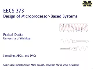
Choosing the sample rate • What sample rate do we need? • Too little: we can’t reconstruct the signal we care about • Too much: waste computation, energy, resources • Example: 2-bytes per sample, 4 kHz 8 kB / second • What about sampling jitter? Remember Lab 1?
Shannon-Nyquist sampling theorem • If a continuous-time signal contains no frequencies higher than , it can be completely determined by discrete samples taken at a rate: • Example: • Humans can process audio signals 20 Hz – 20 KHz • Audio CDs: sampled at 44.1 KHz
Use anti-aliasing filters on ADC inputs toensure that Shannon-Nyquist is satisfied • Aliasing • Different frequencies are indistinguishable when they are sampled. • Condition the input signal using a low-pass filter • Removes high-frequency components • (a.k.a. anti-aliasing filter)
Designing the anti-aliasing filter • Note • w is in radians • w = 2pf • Exercise: Find an R+C pair so that the half-power point occurs at 30 Hz
Direct Samples Dithered Samples Can use dithering to deal with quantization • Dithering • Quantization errors can result in large-scale patterns that don’t accurately describe the analog signal • Introduce random (white) noise to randomize the quantization error.
Outline • Minute quiz • Announcements • Sampling • ADC • DAC
The basics of Analog-to-Digital Conversion • So, how do you convert analog signals to a discrete values? • A software view: • Set some control registers : • Specify where the input is coming from (which pin) • Specify the range (min and max) • Specify characteristics of the input signal (settling time) • Enable interrupt and set a bit to start a conversion • When interrupt occurs, read sample from data register • Wait for a sample period • Repeat step 1
ADC Core • Input • Analog signal • Output • 12-bit digital value of input relative to voltage references • Linear conversion
SAR ADC • SAR = Successive-Approximation-Register • Binary search to find closest digital value • Conversion time log(bits)
SAR ADC • SAR = Successive-Approximation-Register • Binary search to find closest digital value 1 Sample Multiple cycles
SAR ADC 1 Sample Multiple cycles
Timing driven by: TimerA TimerB Manually using ADC12SC bit Signal selection using SHSx Polarity selection using ISSH Sample and Conversion Timing
Voltage Reference • Voltage Reference Generator • 1.5V or 2.5V • REFON bit in ADCCTL0 • Consumes energy when on • 17ms settling time • External references allow arbitrary reference voltage • Exercise: If you want to sample Vcc, what Vref should you use?
Sample Timing Considerations • Port 6 inputs default to high impedance • When sample starts, input is enabled • But capacitance causes a low-pass filter effect Must wait for the input signal to converge
How it looks in code: ADC12CTL0 = SHT0_2 | REF1_5V | REFON | ADC12ON; ADC12CTL1 = SHP; Software Configuration
12 possible inputs 8 external pins (Port 6) 1 Vref+ (external) 1 Vref- (external) 1 Thermistor 1 Voltage supply External pins may function as Digital I/O orADC. P6SEL register Inputs and Multiplexer
16 sample buffer Each buffer configures sample parameters Voltage reference Input channel End-of-sequence CSTARTADDx indicates where to write next sample Conversion Memory
Single-Channel Single-Conversion Single channel sampled and converted once Must set ENC (Enable Conversion) bit each time Sequence-of-Channels Sequence of channels sampled and converted once Stops when reaching ADC12MCTLx with EOS bit Repeat-Single-Channel Single channel sampled and converted continuously New sample occurs with each trigger (ADC12SC, TimerA, TimerB) Repeat-Sequence-of-Channels Sequence of channels sampled and converted repeatedly Sequence re-starts when reaching ADC12MCTLx with EOS bit Conversion Modes
How it looks in code: Configuration ADC12CTL0 = SHT0_2 | REF1_5V | REFON | ADC12ON; ADC12CTL1 = SHP; ADC12MCTL0 = EOS | SREF_1 | INCH_11; Reading ADC data m_reading = ADC12MEM0; Software Configuration
A Software Perspective command void Read.read() { ADC12CTL0 = SHT0_2 | REF1_5V | REFON | ADC12ON; ADC12CTL1 = SHP; ADC12MCTL0 = EOS | SREF_1 | INCH_11; call Timer.startOneShot( 17 ); } event void Timer.fired() { ADC12CTL0 |= ENC; ADC12IE = 1; ADC12CTL0 |= ADC12SC; } task void signalReadDone() { signal Read.readDone( SUCCESS, m_reading ); } async event void HplSignalAdc12.fired() { ADC12CTL0 &= ~ENC; ADC12CTL0 = 0; ADC12IE = 0; ADC12IFG = 0; m_reading = ADC12MEM0; post signalReadDone(); }
A Software Perspective command void Read.read() { ADC12CTL0 = SHT0_2 | REF1_5V | REFON | ADC12ON; ADC12CTL1 = SHP; ADC12MCTL0 = EOS | SREF_1 | INCH_11; call Timer.startOneShot( 17 ); } event void Timer.fired() { ADC12CTL0 |= ENC; ADC12IE = 1; ADC12CTL0 |= ADC12SC; } task void signalReadDone() { signal Read.readDone( SUCCESS, m_reading ); } async event void HplSignalAdc12.fired() { ADC12CTL0 &= ~ENC; ADC12CTL0 = 0; ADC12IE = 0; ADC12IFG = 0; m_reading = ADC12MEM0; post signalReadDone(); }
A Software Perspective command void Read.read() { ADC12CTL0 = SHT0_2 | REF1_5V | REFON | ADC12ON; ADC12CTL1 = SHP; ADC12MCTL0 = EOS | SREF_1 | INCH_11; call Timer.startOneShot( 17 ); } event void Timer.fired() { ADC12CTL0 |= ENC; ADC12IE = 1; ADC12CTL0 |= ADC12SC; } task void signalReadDone() { signal Read.readDone( SUCCESS, m_reading ); } async event void HplSignalAdc12.fired() { ADC12CTL0 &= ~ENC; ADC12CTL0 = 0; ADC12IE = 0; ADC12IFG = 0; m_reading = ADC12MEM0; post signalReadDone(); }
A Software Perspective command void Read.read() { ADC12CTL0 = SHT0_2 | REF1_5V | REFON | ADC12ON; ADC12CTL1 = SHP; ADC12MCTL0 = EOS | SREF_1 | INCH_11; call Timer.startOneShot( 17 ); } event void Timer.fired() { ADC12CTL0 |= ENC; ADC12IE = 1; ADC12CTL0 |= ADC12SC; } task void signalReadDone() { signal Read.readDone( SUCCESS, m_reading ); } async event void HplSignalAdc12.fired() { ADC12CTL0 &= ~ENC; ADC12CTL0 = 0; ADC12IE = 0; ADC12IFG = 0; m_reading = ADC12MEM0; post signalReadDone(); }
A Software Perspective command void Read.read() { ADC12CTL0 = SHT0_2 | REF1_5V | REFON | ADC12ON; ADC12CTL1 = SHP; ADC12MCTL0 = EOS | SREF_1 | INCH_11; call Timer.startOneShot( 17 ); } event void Timer.fired() { ADC12CTL0 |= ENC; ADC12IE = 1; ADC12CTL0 |= ADC12SC; } task void signalReadDone() { signal Read.readDone( SUCCESS, m_reading ); } async event void HplSignalAdc12.fired() { ADC12CTL0 &= ~ENC; ADC12CTL0 = 0; ADC12IE = 0; ADC12IFG = 0; m_reading = ADC12MEM0; post signalReadDone(); }
Interrupts and Tasks command void Read.read() { ADC12CTL0 = SHT0_2 | REF1_5V | REFON | ADC12ON; ADC12CTL1 = SHP; ADC12MCTL0 = EOS | SREF_1 | INCH_11; call Timer.startOneShot( 17 ); } event void Timer.fired() { ADC12CTL0 |= ENC; ADC12IE = 1; ADC12CTL0 |= ADC12SC; } task void signalReadDone() { signal Read.readDone( SUCCESS, m_reading ); } async event void HplSignalAdc12.fired() { ADC12CTL0 &= ~ENC; ADC12CTL0 = 0; ADC12IE = 0; ADC12IFG = 0; m_reading = ADC12MEM0; post signalReadDone(); } Application Kernel Driver MCU ADC
Outline • Minute quiz • Announcements • Sampling • ADC • DAC
A binary-scaled DAC architecture in linear and folded forms • Much more efficient • Monotonicity not guaranteed • May experiences glitches
DAC output signal conditioning • Often use a low-pass filter • May need a unity gain op amp for drive strength
Questions? Comments? Discussion?