Download
1 / 41
420 likes | 557 Views
Adjustable Universal Gold Medal Sailing Seat. Andrew Sulik Timothy Slattery Marion Paredes Pages Derek Topper Detailed Design Review 2/8/13, 3:30 pm. Agenda. Meeting Purpose Overview of Project Review Customer Needs & Eng. Specifications Review Decomposition of System Detailed Design

E N D
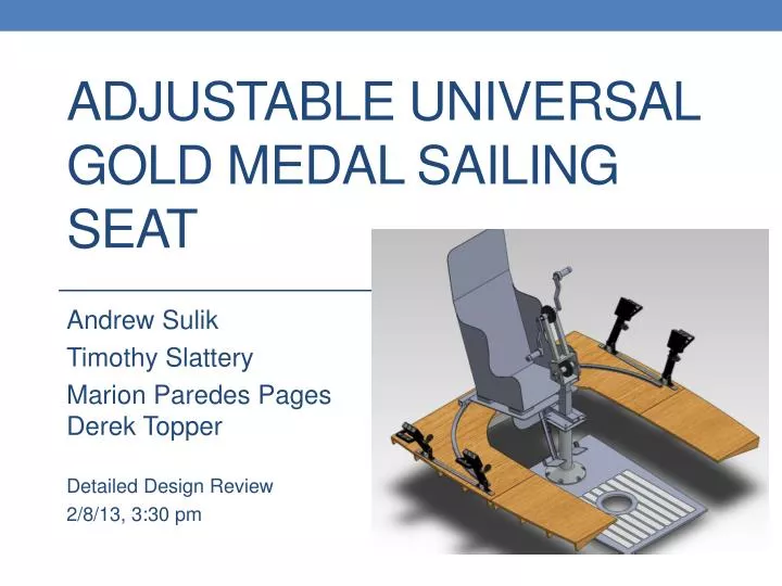
Adjustable Universal Gold Medal Sailing Seat Andrew Sulik Timothy Slattery Marion Paredes PagesDerek Topper Detailed Design Review 2/8/13, 3:30 pm
Agenda • Meeting Purpose • Overview of Project • Review Customer Needs & Eng. Specifications • Review Decomposition of System • Detailed Design • Test Plan • Review Project Plan • Review Risk Assessment • Conclusions
Project Goals • Make system comfortable and adjustable to multiple users • Allow enough room for the use of a jib transfer bench • Increase and/or maintain the functionality already available • Adapt for any C4-5 quadriplegic user such as Richard Ramos on a 3 person Sonar keel boat that meets all IFDS regulations
Customer Needs Recap *1=Most important
Engineering Specs Recap *1 For importance level 1 is must have, 2 is nice to have, 3 is preference only
Ergonomics & Adjustability • 95th Percentile Males – 5th Percentile Females • Accommodate 90% of the population • Backrest • Proper back support • Minimum 10° rearward tilt ✓ • Handles/Hand Grips • Neutral wrist position • Interchangeable for C5 gloves and regular grips • 30° angle 30°
Adjustability – Detailed Design 30º • Considerations: • Distance from shoulders • Shoulder-forward • Shoulder-down • Distance from knees • Distance between legs • Rotation effects and distance 3 in 3 in 3 in 7 in
Adjustability – Detail Design • Crank Up/Down • Below shoulder • Accommodate user’s preference
Adjustability – Detailed Design • Seat Up/Down • Height • Comfort • Seat Back/Forth • Distance from crank • Foot Rests Up/Down • Leg length • Detachable • Foot Rests Angle • Comfort/Disability
Material Selection • Selection criteria • Good corrosion resistance • Good strength • Readily available • Easy to weld • Ideal Material • Aluminum 6061-T6 • Yield Strength 40 ksi • Tensile Ultimate 45 ksi • Young’s Modulus 10 ksi
Fastener Material Selection • Fastener Material • 316 Stainless Steel • Limited Galvanic Corrosion • Cheap and readily available • Yield Strength 34 ksi • Tensile Ultimate 79 ksi • Galvanic Corrosion • Reduced by material selection • Reduced by Delrin washers at all bolts
States of Loading • Worst Case (P12031) • 170 lb applied horizontally to hand crank • 150 lb applied downward on collection barrel • 1349 lb impact force applied to end of track
Detailed Design-Track Platform • Similar to original design – ½” thick marine fir • Aluminum L-beam (underneath) adds support to track platform • Added 2 detachable pieces in the front • Secured using dovetail tabs • Drilled holes in plates on allow for the adjustment of handle locks • Rubber plugs are used to eliminate sharp edges and corners on the handle locks
Track Platform Analysis Track deflection with load Max deflection = 0.1224 in Max deflection = 0.2960 in
Track Platform Analysis • Stress on bolts during impact of 1349 lb (worst case. From P12031.) • Shear strength = 30000 psi • ¼”-20 aluminum bolts – Stainless Steel bolts to be used
Detailed Design-Pedestal Base • Clamping fixture same as P12031 • Platform extended aft 3 in to accommodate Jib Transfer Bench • Support Ribs contoured to boat deck
Detailed Design-Pedestal • Swivel plate provides rotation and deceleration • Pedestal will interface with swivel via welded plate or bolt pattern • Maximum loading parameters determined by manufacturer
Pedestal Forces • MA=MB=2804.88 lb*in • RB=260 lb • Specified at 750lb compression (Trendler) • Specified moment of 9000 lb*in (Trendler) 13 in
Detailed Design-User Support • Seat support frame from P12031 • Main support arm fixed to top of swivel plate
Main Support Arm • δyA = 0.29 in • M = 2804.88 (in*lbs) • σ = 7250.0 psi • σy for 6061-T6 Aluminum is 45,000 psi. • FOS = 6.2 δ σ =
Detailed Design-Hand Crank • Centered pulley system allows individual barrels • Telescoping tube allows vertical adjustment • Center pivot allows space for user entry • Adjustable tensioner allows for easy set up
Detailed Design-Crank Support Arms • Case 1 (worst case) • Fa=170 lb • Mb=838.68 lbin/arm • σ=11981.14 psi/arm • σy=45 ksi (6061-T6) • FOS=3.76 σ =
Detailed Design-Crank Support Arms • Case 2 (normal conditions) • Fa=20 lb • Mb=98.76 lbin/arm • σ=1409.57 psi/arm • σy=45 ksi (6061-T6) • FOS=31.9 σ =
Detailed Design-Rotation Pin • Since bearing cannot apply moment, need pin to lock crank arm into place • These calculations still need to be completed
Detailed Design-Hand Crank • Lower pulley axle • Aluminum 6061-T6 • Yield strength:45000 psi
Detailed Design-Hand Crank • Upper pulley axle • Same properties as before
Hand Crank Fatigue • From quadsailor.com, we found evidence of 3 hour trips • Assuming a 5 month season, 1 tack every 5 minutes, and 4 cranks per tack we get 8460 rev/season • Based on a life of 8 years you get a lifetime use of 69,120 revolutions • Due to this low number, fatigue analysis on these axles is unnecessary
Hand Crank Gearing • Goal: 4 cranks for 90 degree tiller movement • Want to keep 4” load pulley • Based on current system, where 3 cranks give 90 degree tiller movement, we have a 1.25 pulley ratio • To get 4 cranks, need pulley ratio of 0.9375 • Requires 3.75” drive pulley – Not Readily Available • Using 1 pulley ratio need 3.75 cranks for 90 degree tiller movement
Hand Crank Gearing • Options for gearing • Keep current gear ratio with 3 cranks per 90 degree tiller rotation • Use decreased gear ratio with 3.75 cranks per 90 degree tiller rotation • Options to be given to Richard Ramos
Detailed Design-Hand Crank Grips • System designed to mimic C5 grips • Detent pin to keep hands in place • Detent pin axial pull out force needs to be acquired
Bearing Specifications • Sealed bearings to last in elements • Able to withstand larger loads than applied • Cheap to replace if needed
Tiller Strut • Same structure as P12031 • Hasp fitting connection removed • Replaced with clamp • Clamp geometry has not been determined
Emergency Tiller Release • Cam cleat concept has not been fully developed • Requires testing of cam cleats (on Skip’s boat)
Preliminary Test Plan • MSDII Test Plan • See Excel Spread Sheet
Project Plan • MSDI final Project Plan • See .pdf Files • https://edge.rit.edu/edge/P13032/public/WorkingDocuments/Project%20Information/General%20Information/Project%20Plan%20/Project%20Plan%20MDSI%201_4.pdf
Risk Assessment • Overall assessment of risks • See Excel Spreadsheet