Download
1 / 177
1.77k likes | 1.87k Views
This course covers concepts of renewable energy resources, energy-saving illumination, electric heating and welding methods, solar radiation and collectors, and wind energy utilization.

E N D
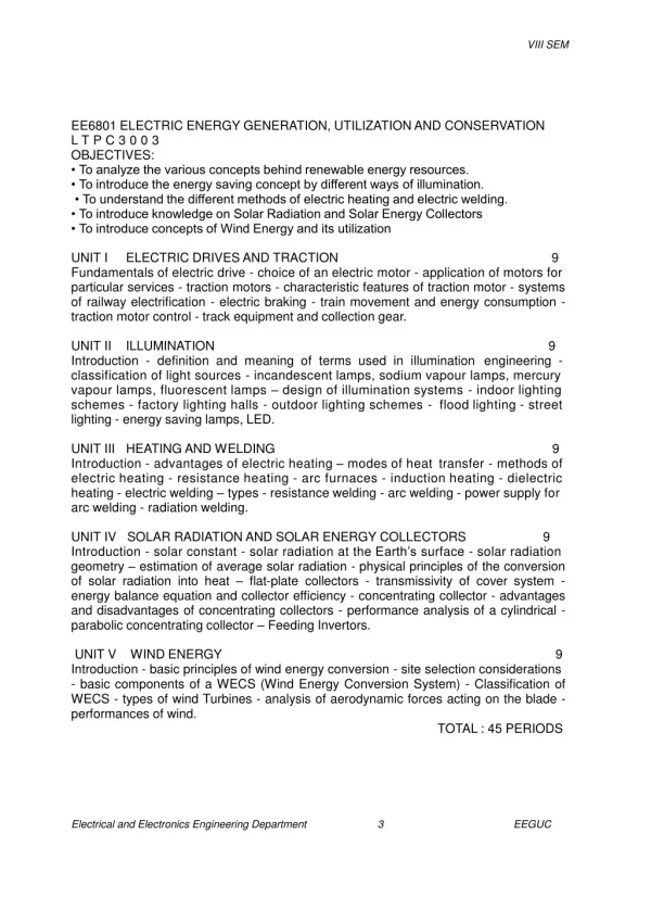
VIII SEM EE6801 ELECTRIC ENERGY GENERATION, UTILIZATION AND CONSERVATION L T P C 3 0 0 3 OBJECTIVES: • To analyze the various concepts behind renewable energy resources. • To introduce the energy saving concept by different ways of illumination. • To understand the different methods of electric heating and electric welding. • To introduce knowledge on Solar Radiation and Solar Energy Collectors • To introduce concepts of Wind Energy and its utilization UNIT I ELECTRIC DRIVES AND TRACTION 9 Fundamentals of electric drive - choice of an electric motor - application of motors for particular services - traction motors - characteristic features of traction motor - systems of railway electrification - electric braking - train movement and energy consumption - traction motor control - track equipment and collection gear. UNIT II ILLUMINATION 9 engineering - Introduction - definition and meaning of terms used in illumination classification of light sources - incandescent lamps, sodium vapour lamps, mercury vapour lamps, fluorescent lamps – design of illumination systems - indoor lighting schemes - factory lighting halls - outdoor lighting schemes - lighting - energy saving lamps, LED. flood lighting - street UNITIII HEATINGANDWELDING Introduction - advantages of electric heating – modes of heat 9 transfer - methods of electric heating - resistance heating - arc furnaces - induction heating - dielectric heating - electric welding – types - resistance welding - arc welding - power supply for arc welding - radiation welding. UNITIV SOLAR RADIATIONANDSOLARENERGYCOLLECTORS 9 Introduction - solar constant - solar radiation at the Earth’s surface - solar radiation geometry – estimation of average solar radiation - physical principles of the conversion of solar radiation into heat – flat-plate collectors - transmissivity of cover system - energy balance equation and collector efficiency - concentrating collector - advantages and disadvantages of concentrating collectors - performance analysis of a cylindrical - parabolic concentrating collector – Feeding Invertors. UNIT V WIND ENERGY 9 Introduction - basic principles of wind energy conversion - site selection considerations - basic components of a WECS (Wind Energy Conversion System) - Classification of WECS - types of wind Turbines - analysis of aerodynamic forces acting on the blade - performances of wind. TOTAL : 45 PERIODS Electrical and Electronics Engineering Department 3 EEGUC
VIII SEM OUTCOMES: Abilitytounderstandandanalyzepowersystemoperation,stability,controland protection. Abilitytohandletheengineeringaspectsofelectricalenergygenerationand utilization. TEXT BOOKS: 1. N.V. Suryanarayana, “Utilisation of Electric Power”, Wiley Eastern Limited, New Age International Limited,1993. 2. J.B.Gupta, “Utilisation Electric power and Electric Traction”, S.K.Kataria and Sons, 2000. 3. G.D.Rai, “Non-Conventional Energy Sources”, Khanna Publications Ltd., New Delhi, 1997. AULibrary.com 82 REFERENCES: 1. R.K.Rajput, Utilisation of Electric Power, Laxmi publications Private Limited.,2007. 2. H.Partab, Art and Science of Utilisation of Electrical Energy”, Dhanpat Rai and Co., New Delhi, 2004. 3. C.L.Wadhwa, “Generation, Distribution and Utilisation of Electrical Energy”, New Age International Pvt.Ltd., 2003. 4. S. Sivanagaraju, M. Balasubba Reddy, D. Srilatha,’ Generation and Utilization of Electrical Energy’, Pearson Education, 2010. 5. Donals L. Steeby,’ Alternative Energy Sources and Systems’, Cengage Learning, 2012 Electrical and Electronics Engineering Department 4 EEGUC
VIII SEM Unit – I Electric Drives and Traction Part – A 1. What is scheduled speed of train? [CO1 – L1 - APRIL/MAY 2008 ] Theratio of distancecovered betweentwostops andtotal timeofrunincluding time ofstopis knownas schedulespeed.Schedulespeed=Distancebetweenstopsin km/Actual timeofrunin hours + stoptimeinhours.Theschedulespeedis always smaller thantheaveragespeed.The differenceis largeincaseofurbanandsuburban services andis negligiblysmallincase of mainlineservice. 2. What is load equalization? [ CO1 – L1 - APRIL/MAY 2008, MAY/JUNE 2009]. When heavyloadis applied,themotor speeddecreases andflywheel will supplykinetic energyto themotor.Duringlightloadcondition,themotor speed increasesandtheflywheel storestheenergy.Thus theloadonthemotor is equalized. Sowe defineloadequalization as “duringtheoperation of drives,loadtorque fluctuates widely within shot intervals of time this may cause more problems and affect the stability of the drive. These problems of fluctuating loads are overcome by mounting a flywheel on the motor shaft in non-reversible drives”. This process is known as load equalization. 3. Distinguish between individual drive and group drive.[ CO1 – L1 - APR 2008] Group electric drive The group electric drive was used in the earlier days. It had a single motor of sufficient capacity to drive an entire group of machines used in a shop. The motor was connected to a line shaft and through the use of belts and pulleys all the machines were driven. This form of drive was very inefficient, difficult to control and unsafe. 4. Define tractive effort. [ CO1 – L1 - NOV /DEC 2008, APR 2014] The effective force necessary to propel the train at the wheels of the locomotive to which the motor is geared is called the tractive effort. It is measured in Newtons and is tangential to the driving wheels 5. What is meant by specific energy consumption? [ CO1 – L1 - NOV 2008, APR 2015] The energy input to the motors which gives tractive effort is called the energy consumption of the train, since it is the energy consumed for propelling the train. The total energy drawn from the distribution system will be greater than this by the quantity required for lighting, heating, and control and braking. Electrical and Electronics Engineering Department 6 EEGUC
VIII SEM 6. What are the advantages of individual drive? [ CO1 – L1 - NOV /DEC 2008] The advantages are If there is a fault in one motor, the effect on the production or output of the industry will not be appreciable Machines can be located at convenient places Continuity in the production of the industry is ensured to a higher degree. 7. What type of electrical drive is used in (a) cranes (b) blowers? [ CO1 – L1 - NOV /DEC 2008] Cranes: DC series motor and AC Schrage motor Blowers:DCshunt motor andAC single phaseinduction motors andsynchronous motors. 8. List two merits of series-parallel starting of traction motors. [CO1 – L1 - MAY/JUNE 2009] Efficiency is more Without wasting energy, more than one economical speed is possible The energy lost in the starting resistance is low 9. What are the factors affecting specific energy consumption [ CO1 – L1 – APR 2015, MAY/JUNE 2009] Distance between the stops Train resistance Acceleration and retardation Gradient Type of train equipment. 10. What is meant by electrical drives? [ CO1 – L1 ] Systems employedformotioncontrol arecalled“DRIVES”anddrives employanyof theprimemovers suchas, diesel orpetrolengines,gas or steam turbines,hydraulic motors and electric motorsfor supplyingmechanicalenergyformotioncontrol. Drives employingelectric motionknown as “ElectricDrives”. 11. Define an electric drive. [ CO1 – L1 ] Thecombinationof anelectric motor, theenergytransmittingshaft andthecontrolling devicesfor controllingtheperformanceofthemotor is calledanelectric drive 12. What are the essential requirements of braking in an electrical drive? [CO1- L1] 1. Fast reliable and controllable 2. Stored energy should be dissipated efficiently 3. Failure in any part should result in braking only. Electrical and Electronics Engineering Department 7 EEGUC
VIII SEM 13. State the merits and de merits of electrical braking. [CO1 – L1 ] Merits: Less maintenance No dirt Regenerative braking Possible Demerits: Motor should have suitable braking characteristics. No holding torque During failure of supply mechanical braking needed 14. Define and mention different types of braking in a dc motor? [ CO1 – L1 ] In braking,themotorworks as ageneratordevelopinga negativetorquewhich opposes themotion.Types ofregenerative brakingare Dynamic (or)Rheostatbraking; andplugging(or)reversevoltage braking. 15. What is meant by regenerative braking? [ CO1 – L1 ] Regenerative brakingoccurs when themotor speed exceedsthesynchronous speed.In this case,theinduction motor wouldrunsas theinductionmachineis convertingthemechanical power into electrical power, whichis deliveredback to the electrical system.Thismethod of brakingis known as regenerative braking. 16. What is meant by dynamic braking? [ CO1 – L1 ] Dynamic braking of electric motor occurs when theenergystoredintherotating mass isdissipatedin an electrical resistance.This requires themotor to operate asa generator toconvert this storedenergyinto electrical. 17. What is meant by plugging? [ CO1 – L1 ] Itis onemethod of brakingofinduction motor.Whenphasesequenceofsupply ofthemotor runningataspeedis reversed,byinterchangingconnections ofanytwo phases ofstator withrespecttosupplyterminals, operationshiftsfrom motoringto pluggingregion. 18. Give the merits and demerits of group drive. [ CO1 – L1 - MAY/JUNE 2009] Merits: Initial cost of installing the drive is low Incertainindustryprocesses oneprocess is connectedtoanother process and it will be advantageousif alltheseinterconnectedprocessesare stopped simultaneously. Demerits: If at certain instance all the machines are not in operation, then the motor will be working at low capacity It is not possible to install any machine at a distance place. The possibility of installation of additional machines in an existing industry is limited Electrical and Electronics Engineering Department 8 EEGUC
VIII SEM In case of fault in the motor all the machines connected to this motor will cease to operate thereby paralyzing either complete or part of the industry until the time the fault is removed. 19. With respect to the traction systems, explain the term ‘free running’.[ CO1 – L1 - NOV/DEC 2009] There are five distinct periods in the running of train Notching up period Accelerationperiod Freerunningperiod Coastingperiod Brakingperiod In traction system, free running is the status of train run which indicates the train runs at constant speed attained at the end of speed curve running. Freerunning period:Duringthis periodonlevel track thepower outputfromthe drivingaxle balances therate at which energyis expended againsttheresistanceto motion.Attheend ofspeedcurverunningtrainreachesmaximumspeed. 20. What is the voltage level used in traction distribution network? [ CO1 – L1 - NOV/DEC 2009] DC system: 1500 V to 3000 V (AC source is 33KV) 25 KV single phase AC systems: voltage level used to 300V to 400 V at 25 or 16.67 Hz Three phase system: voltage level used is 300 V to 3600V at normal frequency or 16.67 Hz Finally the distribution network is fed at voltage varying between 15Kv to 25Kv at normal frequency at 50Hz.The ac supply is stepped down and converted to dc. 21. Write the applications of DC shunt motor. [ CO1 – L1 - NOV/DEC 2009] Themaincharacteristics ofd.c.shuntmotor are its nearlyconstantspeed over wide rangeofloading andits abilityof operatingatanyspeedwithinawiderange.Shunt motor mostlyusedforconstantspeedapplications Lathe machines Drilling machines Grinder Line shafting and fans. 22. Name two types of loads, related to electrical drives. [ CO1 – L1 – NOV 2009] Active loads: which are due to the forces of gravity, tension or compression. Active loads are independent of loads, ex: paper mill drive. Passive loads:whichare dueto thefriction,cuttinganddeformationofinelastic bodies.Exampleforpassiveloads isfans,compressors, airplanes,centrifugal pumps, ship propellers, highspeed hoists,tractionetc. Electrical and Electronics Engineering Department 9 EEGUC
VIII SEM 23. What type of motor is used for electric traction? Why? [ CO1 – L1 - MAY 2010] Series and compound motors are employed in d.c traction systems. D.C series motor Advantages High starting torque Simple speed control Better commutation up to twice full load Simple and robust in construction Less susceptible to variations in supply voltage Capable of withstanding excessive loads. These motors are more particularly suitable for suburban and urban services where high rate of acceleration is essential. A.C SeriesMotorManysingle phasea.c. motors have beendevelopedfor traction purposes butonlycompensatedseries typecommutatormotor is bestsuitedfor traction.Single phaseinductionmotors arenotcapable of developinghighstarting torque henceitis notused. Advantages Higher efficiency Improved commutation The weight per kw output is greater for the higher frequency because of larger dimensions of the motor. Efficient speed control of motor by providing taps on a transformer which is not possible in d.c series motor. Thesemotors areusedformainlineservices.Thesearenotsuitablefor urban andsuburbanservices because oflowstartingtorque andpoor power factorat start. 24. What are the requirements of an ideal traction system? [ CO1 – L1 ] The requirements of an ideal traction system are as follows The starting tractive effort should be high so as to have rapid acceleration. The wear on the track should be minimum. Pollution free Speed control should be easy. The equipmentshouldbecapableofwithstandinglarge temporaryloads. Lowinitial andmaintenancecost. There shouldbenointerference tothecommunicationlines runningalongthe lines. Braking should be such that minimum wear is caused on the brake shoes. 25. Name the various systems of traction. [ CO1 – L1 ] Direct steam engine drive Direct Internal Combustion Engine Drive Steam Electric Drive Internal Combustion Engine Electric Drive Electrical and Electronics Engineering Department 10 EEGUC
VIII SEM Petrol Electric traction Electric Drive 26. Classify the supply system for electric traction. [ CO1 – L1 ] D.C system A.C system Single phase Threephase Composite system Single phase AC-DC single phase-Threephase 27. What are the advantages of electric traction? [ CO1 – L1 – NOV 14] High starting torque Less maintenance cost Cheapest method of traction Rapid acceleration and braking Less vibration Coefficient of adhesion is better It has great passenger carrying capacity at higher speed. 28. What are the disadvantages of electric traction? [ CO1 – L1 – NOV 14 ] High capital cost Problem of supply failure Additional equipment is required for achieving electric braking and control Theleakageofcurrentfromthedistribution mainsand drop ofvolts in the track are tobekept withinthe prescribedlimits. The electrically operated vehicles have to move on guided track only. 29. Name the different stages of train movement [ CO1 – L1 ] Acceleration Constant speed or free running Coasting, running with power switched off and brake not applied Retardation, with braking 30. What are the essential features (electrical )of an ideal traction motor [ CO1 – L1 ] High starting torque. Series speed torque characteristics Simple speed control Possibility of regenerative braking Electrical and Electronics Engineering Department 11 EEGUC
VIII SEM 31. What is the need for traction motor control? [ CO1 – L1 ] To limit starting current 2Smooth acceleration without jerk Both manual and automatic control should be possible. 32. Give any two advantages of electric traction. [ CO1 – L1 - APRIL/MAY 2010] Advantages of electric traction High starting torque Less maintenance cost Cheapest method of traction Free from smoke and fluke gases hence used for underground and tubular and braking Less vibration Coefficient of adhesion is better It has great passenger carrying capacity at higher speed. 33. Define continuous rating of motor. [ CO1 – L1 - APRIL/MAY 2010] Itis theoutputwhichamotor can givecontinuouslyfor longtimewithout exceedingthegiven temperature riseand themotor shouldbeabletogive 20% overloadfor two hours 34. Why is induction motor commonly preferred drive industrial application? [ CO1 – L1 - APRIL/MAY 2010] Thoughthree-phaseinductionmotorshave the advantages ofsimple androbust construction,highvoltage operation,less maintenanceetc.,theyarecommonlyused for industrial application due to their flat speed torque characteristics, constant speed operation, and low starting torque. Advantages of AC 3 phase induction motors. It has very simple and extremely rugged, almost unbreakable construction especially squirrel cage type. Its cost Is low and it is very reliable It has sufficiently high efficiency. In normal running condition, no brushes are needed, hence frictional losses are reduced. It has a reasonably good power factor It requires minimum maintenance it start upfromrestand needsnoextrastartingmotor andhas notto be synchronized.Its startingarrangementis simple especiallyfor squirrel cage type motor. 35. List the factors affecting scheduled speed of a train. [ CO1 – L1 - MAY 2011] The scheduled speed of a train when running on a given service is affected by the following factors: i Acceleration & braking retardation If the acceleration and braking retardation increases with fixed crest speed for a given run, the schedule speed increase which results in decrease of actual time of run. ii) Maximumorcrest speedIfthecrestspeedincreases incase ofcityand Electrical and Electronics Engineering Department 12 EEGUC
VIII SEM suburban service, the coasting period and time taken for particular value of accelerating period reduces. Hence schedule speed increases. iii)Stopping timeorduration ofstopThestoppingtime affectstheschedule speedinthewaythatincrease ofstoppingtimereduces theschedulespeed. This isofparticular significanceincaseofshort runs where thestopping time is more compared to total of run. In case of main line service this is not much significance. 36. Define continuous rating of a motor. [ CO1 – L1 - APRIL / MAY 2011] Itis theoutputwhichamotor can givecontinuouslyfor longtimewithout exceedingthegiven temperature riseand themotor shouldbeabletogive 20% overloadfor two hours. 37. What do you mean by average speed in electric traction? [ CO1 – L1 ] The mean of the speeds from the start to stop i.e the distance between two stops divided by the actual time of run is known as average speed. 38. What do you mean by schedule speed in electric traction? [ CO1 – L1 ] The ratio of distance covered between two stops and total time of run including time ofstopis knownas schedulespeed.Theschedulespeedis always smaller than theaveragespeed.The differenceis largeincaseof urbanandsuburbanservices and is negligiblysmallincaseof mainlineservice. 39. Define dead weight, adhesive weight. [ CO1 – L1 ] (i) DeadweightThetotal weight oflocomotive andtraintobepulledbythelocomotive is known as deadweight. (ii) Adhesive weight The total weight to be carried on the driving wheels is known as the adhesive weight. 40. Name the various methods of traction motor control. [ CO1 – L1 ] There are various methods for controlling the speed of d.c series motors. They are Rheostatic control Series parallel control Field control Buck andBoostmethod Metadynecontrol Thyristor control 41. What are the basic requirements of braking system? [ CO1 – L1 ] The basic requirements of a braking system are given below It should be simple, robust, quick and reliable in action. Easy to use for driver to operate. Maintenance should be minimum. Electrical and Electronics Engineering Department 13 EEGUC
VIII SEM The braking system should be inexhaustible. Incaseofemergencybraking,safetyconsiderationis takenintoaccount. Kinetic energyofthetrainmustbestorableduringbrakingwhichcouldbe used subsequentlyduringacceleration ofthetrain. 42. What are the various methods of applying electric braking? [ CO1 – L1 ] There are three methods of applying electric braking are Plugging or Reverse current braking. Rheostatic braking. Regenerative braking. 43. Name the advanced methods of speed control of traction motors. [CO1 – L1 ] The latest methods of speed control of traction motors are Tap changer control Thyristor control Chopper control Microprocessor control 44. What are the advantages of microprocessor based control of traction motors? [ CO1 – L1 ] High speed of response High accuracy Over voltage and over speed protection. Electronic interlocking Less sensitive to temperature variationsanddrift. Numbers ofcomponents used are less. Electrical and Electronics Engineering Department 14 EEGUC
VIII SEM Part-B Explain the working of the Traction system. [ CO1 – L2] The locomotive in which the driving or tractive force is obtained from electric motors is called Electric traction. Electric traction has many advantages as compared to other non-electrical systems of traction including steam traction. Electric traction is used in: i) Electric trains ii) Trolley buses iii) Tram cars iv) Diesel-electric vehicles etc. Traction systems All traction systems, broadly speaking, can be classified as follows: 1. Non-electric traction systems: These systems do not use electrical energy at some stage or the other. Examples: (i) Steam engine drive used in railway (ii) Internal combustion-engine-drive used for road transport 2. Electric traction systems: These systems involve the use of electric energy at some stage or the other. These are further sub divided into the following two groups: a) Self contained vehicles or locomotives Examples: i) Battery-electric drive ii) Diesel-electric drive b) Vehicles which receive electric power from a distribution network or suitably placed sub- stations. Examples: i) Railway electric locomotive fed from overhead A.C supply; ii) Tramways and trolley buses supplied with D.C. supply. 1. 2. List out the Requirements of an ideal traction system.[ CO1 – L2 – APR 2014] The requirements of an ideal traction systemare: 1. High adhesion coefficient, so that high tractive effort at the start is possible to have rapid acceleration. 2. The locomotive or train unit should be self contained so that it can run on any route. 3. Minimum wears on the track. 4. It should be possible to overload the equipment for short periods. 5. The equipment required should be minimum, of high efficiency and low initial and maintenance cost. 6. It should be pollution free. 7. Speed control should be easy. 8. Braking should be such that minimum wear is caused on the brake shoes, and if possible the energy should be regenerated and returned to the supply during braking period. Electrical and Electronics Engineering Department 15 EEGUC
VIII SEM 9. There should be no interference to the communication lines running the track. 3. What are all the Advantages and Disadvantages of Electric Traction? [ CO1 - L2 ] Advantages and Disadvantages of Electric Traction Electric traction system has many advantages compared to non-electric traction systems. The following are the advantages of electric traction: Electric traction system is more clean and easy to handle. No need of storage of coal and water that in turn reduces the maintenance cost as well as the saving of high-grade coal. Electric energy drawn from the supply distribution system is sufficient to maintain the common necessities of locomotives such as fans and lights; therefore, there is no need of providing additional generators. The maintenance and running costs are comparatively low. The speed control of the electric motor is easy. Regenerative braking is possible so that the energy can be fed back to the supply system during the braking period. Electrical features of a traction system High-starting torque A traction motor must have high-starting torque, which is required to start the motor on load during the starting conditions in urban and suburban services. Speed control The speed control of the traction motor must be simple and easy. This is necessary for the frequent starting and stopping of the motor in traction purpose. Dynamic and regenerative braking Traction motorsshouldbeable to provideeasy simple rheostatic and regenerativebrakingsubjectedtohighervoltagessothatsystemmust have thecapabilityofwithstandingvoltagefluctuations. Temperature The traction motor should have the capability of withstanding high temperatures during transient conditions. Overload capacity The traction motor should have the capability of handling excessive overloads. No single motor can have all the electrical operating features required for traction Explain the various types of electric traction system. [CO1 – L2 - Nov’13, NOV 14 ] The various systems of traction commonly used are, 4. 1. Steam engine drive. 2. Internal combustion engine drive. Electrical and Electronics Engineering Department 16 EEGUC
VIII SEM 3. Internal combustion electric drive. 4. Petro-electric traction. 5. Battery electric drive. 6. Electric drive. Steam engine drive: Steamenginedrive,thoughlosingground gradually dueto various reasons;itisstilltheamplyadoptedmeansofpropulsionof railway work in underdeveloped countries.Inthis type of drive,the reciprocatingengineisinvariablyusedforgettingthenecessary motive power. Advantages Simplicity in design. Simplified maintenance. Easy speed control. Simplicity of connections between the cylinders and the driving wheels. No interference with communication network. Low capital cost as track electrification is not required. Thelocomotiveandtrainunitisselfcontained;therefore,itisnottiedtoa route. It is cheap for low density traffic areas and in initial stages of communication by rail Operational dependability. Disadvantages Low thermal efficiency. Due to the reason of low adhesion coefficient, power- weight ratio of steam locomotive is low. It has strictly limited overload capacity. Steam locomotive cannot be put into service at any moment as time is required for raising of steam. Owing to high centre of gravity of steam locomotive, speed is limited. Steam locomotive requires more repair and maintenance. Extensive and costly auxiliary equipment. Since driving wheels are very close, hence more concentrated adhesive weight is required. Bigger sizes of running sheds and workshop are required. Internal combustion engine drive: This drive is widely used for road transport. The motive power is derived from petrol to diesel. It has an efficiency of about 25 percent when operating at normal speed. Various example are buses, cars, trucks etc., Advantages Low initial investment. It is self-contained unit and, therefore, it is not tied to any route. Easy speed control. Electrical and Electronics Engineering Department 17 EEGUC
VIII SEM Very simple braking system. It is cheap drive for the outer suburbs and country districts. Disadvantages Limited overload capacity. A gear box is essential for speed control. Higher running and maintenance costs. Operation at any but the normal speed is uneconomical. The life of propulsive equipment is much shorter than that of electrical equipment of a tram car or a trolley bus. Internal combustion electric drive: InanI.Cengineelectricdrivethereductiongearandgearbox are eliminatedasthediesel asthedieselengineistodrivetheD.C. generatorcoupledtoitataconstantspeed. Thistypeofdriveisfinding considerablefavourforrailwayworkandlocomotives ofthistype are beingwidelyused. Advantages Low initial investment. No modification of existing tracks is required while converting from steam to electric traction. Asthelocomotiveandtrainisaselfcontainedunit,therefore,itisnotliedto anyroute. Can be put into service at any moment. Loss of power in speed control is very low. It is available for hauling for about 90% of its working days. Overall efficiency is greater than that of steam locomotives. diesel Disadvantages Limited overload capacity. High running and maintenance cost. Higher dead weight of locomotives; more axles required comparatively. Comparatively costlier than steam or electric locomotives. In such drives, regenerative braking cannot be used. The life of the diesel engine is comparatively shorter. There is a necessity to provide special cooling system for the diesel engine in addition to motor-generator set. Petrol-electric traction: This system, due to electric conversion, provides a very fine and continuous control which makes the vehicle capable of moving slowly at an imperceptible speed and creeping up the steepest slope without throttling the engine. Petrol-electric traction is employed in heavy Lorries and buses. Battery electric drive: Inthissystemthelocomotivecarriesthesecondarybatterieswhichsupply powertoD.C.motorsemployedfordrivingthevehicles.Thistypeofdriveiswell Electrical and Electronics Engineering Department 18 EEGUC
VIII SEM suited for frequently operated service such as for local delivery of goods in large towns with maximum daily run of 50 to 60 km, shunting and traction in industrial works and mines. Battery vehicles are started by series-parallel for starting and running at the speed upto half maximum speed and in series for running at full maximum speed. Advantages Battery driven vehicle is easy to control and very convenient to use. Low maintenance cost. Absence of fumes. Disadvantages This type of drive is the small capacity of batteries and the necessity for frequent charging. Limited speed range. Electric drive: Herethe driveis bymeans of electric motorswhich are fedfromoverhead distribution system. The drive of this type is most widely used. Advantages As it has no smoke, electric traction is most suited for the underground and tube railways. The motors used in electric traction have a very high starting torque. Hence, it is possible to achieve higher accelerations of 1.5 to 2.5 km/h/s as against 0.6 to 0.8 km/h/s in steam traction. An electric locomotive is ready to start at moment's notice against about two hours required for steam locomotive to heat up. The maintenance cost of an electric locomotive is 50 percent of that of steam locomotive; its maintenance time is also much less comparatively. By the use of electric traction high grade coal can be saved, since electric locomotives can be fed either from hydroelectric stations or thermal power station which use cheap low-grade coal. In electric traction system it is possible to use regenerative braking. Owing to complete absence of smoke and fumes, this system is healthier from the hygienic point of view. The vibrations in electrically operated vehicles are less as the torque exerted by the electric motor is continuous. Electric equipment can withstand large temporary overloads and can draw relatively large power from the distribution system. Disadvantages Highinitialcostoflayingoutoverheadelectricsupplysystem.Unlessthe traffictobehandledis heavy,electrictractionbecomesuneconomical. Power failure for a few minutes can cause traffic dislocation for hours. The electric traction system is tied up to only electrified routes. Communication lines which usually run parallel to the power supply lines Electrical and Electronics Engineering Department 19 EEGUC
VIII SEM suffer from electrical interference. Hence, these communication lines have either to be removed away from the rail track or else underground cables have to be used for the purpose which makes the system still more expensive. Additional equipment is required for regeneration. In case of D.C. series motors regeneration is not a simple process. In case of electric traction provision of a negative booster is essential. By avoiding the flow of return currents through earth, it curtails corrosion of underground pipe work and interference with telegraph and telephone circuits. Whereas steam locomotives can use their steam for heating the compartmentsincoldweather verycheaply,theelectriclocomotiveshavetodo itatanextracost. In cold countries a service locomotive is required to run up and down the line in order to prevent the formation of layer of ice on the conductor rails. 5. Draw the Speed time curve of traction and also explain the various periods and the action [CO1 – L2 - Nov’13]. Itisthecurvedrawnbetweenspeedoftraininkm/houralongy-axisandtime in secondsalongx-axis.Thespeedtimecurvegivescompleteinformationofthe motionofthetrain.Thiscurvegivesthespeedatvarioustimesafterthestartandrun directly. Thedistancetravelledbythe trainduringa givenintervalof time canbe obtainedbydeterminingthearea betweenthecurveandthetimeaxiscorresponding tothisinterval. Atypicalspeedtimecurveformainlineserviceisshowninfig.This curveconsistsoffivesections. 1. Notching up period (0 to t1): During this period of run (0 to t1), starting resistance is gradually cut so that the motor current is limited to a certain value and the voltage across the motor is gradually increased and the traction motor accelerates from rest. To cut the starting resistance, the starter handle has to be moved from one notch to another. Hence this period is called notching up period. The acceleration is almost uniform during this period. Therefore speed- time curve is a straight line (OA). Electrical and Electronics Engineering Department 20 EEGUC
VIII SEM 2. Acceleration period (t1 to t2) When all the starting resistances are cut out, the full voltage is applied to the motor. Now the torque decreases and speed increases according to the speed torque characteristics of the motor. Now the acceleration gradually decreases with the increase in speed and finally reaches the required torque for the movement of the train (at time t2). 3. Free running period (t2 to t3) Duringthis periodi.e. t2to t3thepower supplied tothemotor isatfullvoltage and speed of this period is constant, also during this period power drawn from the supply is constant. 4. Coasting period (t3 to t4) At the end of free running period supply to the motor is cut off and the train is allowed to run under its own kinetic energy. Due totrainresistancespeedofthe train graduallydecreases. The rate of decreasing of speed during this period is known as "coasting retardation". 5. Braking or retardation period (t4 to t5) At the end of coasting period the brakes are applied to bring the train to stop. During this period speed decreases rapidly and finally reduces to zero. 6. Draw the Speed time curve of a various types of tractionservices.[ CO1 - L2 ] There are three types of electric traction services. 1. Main line service 2. Sub-urban service 3. Urban service Speed - Time curve for main line service: The distance between two successive stations in main line service is considerably more (more than 10 km). In this service free run is longer duration. The duration of acceleration and retardation is small. Electrical and Electronics Engineering Department 21 EEGUC
VIII SEM Speed - Time curve for suburban service In this type of service the distance between two successive stations is in the range of 1.5 km to 8 km. Fig represents speed-time curve for sub- urban service. Acceleration and braking retardation required are high. Freerunningperiodisnotpossibleandcoastingperiodwill becomparatively longer than urbanservice. Speed - Time curve for urban or city service In city service the distance between the two stations is very short i.e., between 0.75 to 1 km. The time required for this run between the adjacent and retardation should be sufficient high. Fig shows the speed-time curve for urban or city service. It will be seen that there will be no free running period. The coasting period is also small. 7. Explain the types of supply system in electric traction.[ CO1 – L2 – NOV14] DC System In this system of traction, the electric motors employed for getting necessary propelling torque should be selected in such a way that they should be able to operate on DC supply. Examples for such vehicles operating based on DC system are tramways and trolley buses. Usually, DC series motors are preferred for tramways and trolley buses even though DC compound motors are available where regenerative braking is desired. The operating voltages of vehicles for DC track electrification system are 600, 750, 1,500, and 3,000 V. Direct current at 600–750 V is universally employed for tramways in the urban areas and for many suburban and Electrical and Electronics Engineering Department 22 EEGUC
VIII SEM main line railways, 1,500–3,000 V is used. 1-φ AC system In this system of track electrification, usually AC series motors are used for getting the necessary propelling power. The distribution network employed for such traction systems is normally 15–25 kV at reduced frequency of 163⅔ Hz or 25 Hz. The main reason of operating at reduced frequencies is AC series motors that are more efficient and show better performance at low frequency. These high voltages are stepped down to suitable low voltage of 300–400 V by means of step-down transformer. Low frequency can be obtained from normal supply frequency with the help of frequency converter. Low-frequency operation of overhead transmission line reduces the line reactance 3-φ AC system Inthissystemoftrackelectrification,3-φinductionmotorsareemployedfor gettingthenecessarypropellingpower.Theoperatingvoltageofinductionmotorsis normally 3,000–3,600-V AC at either normal supply frequency or 16⅔-Hz frequency. Usually 3-φ induction motors are preferable because they have simple and robust construction, high operating efficiency, provision of regenerative braking without placing any additional equipment, and better performance at both normal and seduced frequencies. In addition to the above advantages, the induction motors suffer from some drawbacks; they are low-starting torque, high-starting current, and the absence of speed control. The main disadvantage of such track electrification system is high cost of overhead distribution structure. This distribution system consists of two overhead wires and track rail for the third phase and receives power either directly from the generating station or through transformer substation. Composite system As the above track electrification system have their own merits and demerits, 1-φACsystemispreferableintheviewofdistributioncostanddistributionvoltage canbesteppeduptohighvoltagewiththeuseoftransformers,whichreducesthe transmission losses. Whereas in DC system, DC series motors have most desirable features and for 3-φ system, 3-φ induction motor has the advantage of automatic regenerative braking. So, it is necessary to combine the advantages of the DC/AC and 3-φ/1-φ systems. The above cause leads to the evolution of composite system. Composite systems are of two types. Single-phase to DC system. Single-phase to three-phase system or kando system. Single-phase to DC system In this system,theadvantagesof both1-φ andDC systems arecombinedto get highvoltage for distributionin order toreducethelosses thatcanbeachieved with 1-φ distribution networks, and DC series motor is employed for producing the necessary propelling torque. Finally, 1-φ AC distribution network results minimum cost with high transmission efficiency and DC series motor is ideally suited for Electrical and Electronics Engineering Department 23 EEGUC
VIII SEM traction purpose. Normal operating voltage employed of distribution is 25 kV at normal frequency of 50 Hz. This track electrification is employed in India. 8. Explain how rheostatic braking is employed in traction motors.[CO1-L2] In this method, the motor is disconnected from the supply and operated as a generator driver by the momentum, supplying current to the resistance across the motor, thus dissipating away the energy and coming to a quick stop. Intractionwork,wheretwoormore motorsareemployed,theyareputin parallel acrossaresistance for braking,sinceseriesgivershighvoltage,duringthe braking periodthe motorsaredriven asgeneratorowingtothekineticenergy ofthe trainandelectricalenergysogeneratedisdissipatedintheformofheatin the resistanceconnected acrossthem.Aequalizerconnectionis usedinordertoensure thatthetwomachines sharetheloadequally.Ifnot,the machinethatwouldbuildup firstsendslargecurrentthroughtheotherin theoppositedirectioncausingreversed voltage. Hence the second method is advantageous to the first as if the direction of the machine armature reverses, the machines will fail to excited with equalizer connection and no braking effect is produced. 3 – Phase induction motor: This method cannot be employed. AC Series motor: It is obtained by operating the machines as generators excited from the supply or as self excited DC generators supplying to resistance load. The fields are excited at low voltage from a suitable tap of the main transformer. Fields may be excited from on off motors acting as series generator and de power generated from the other will dissipated through resistive loads. 9. Explain how regenerative braking is employed in traction machines.[CO1-L2] In regenerative braking, the motor remain connected to the supply and return the braking energy to the supply. It is essential that traction motors must generate power at a voltage higher than the supply voltage and at a reasonable constant voltage. DC series Motor: Dc series motor cannot be used for regenerative braking in an ordinary way. The reversal of armature current necessary to produce regeneration would cause reversal of field. At the instant of reversal, short circuit will occur. To overcome these problems, some methods are used. One method of regenerative braking with series motor is the French method. The series motor for trolley bus is equipped with a main series field winding and auxiliary field windings connected in parallel with the main series field windings. Duringbrakingperiod,theauxiliaryfieldwindingsareputinserieswith each otherand areswitched acrossthe supply. The machine acts asacompound generator withslight differential compounding. An alternative method of regenerative braking is by using a separate exciter for Electrical and Electronics Engineering Department 24 EEGUC
VIII SEM controlling the excitation of the field winding during regeneration. The exciter may either be axle driven by a motor operated from the auxiliary supply. Induction Motor: Regenerative braking with three phase induction motor occurs automatically when the motor runs at a speed slightly above the synchronous. It then works as an induction generator. Inductiongeneratoris notself–excitingandmustbeconnectedtoasystem supplied fromsynchronousgenerator,itcanbeemploybyanyoneofthefollowing processes. Switching over from high – low frequency supply in order to reduce the speed of the drive. Downward motion of a loaded hoisting mechanism. Switching over to a larger pole number of operation from a smaller one in multi- speed squirrel cage motors. Single phase series motors: Braking with AC series motor is much more complicated as compared to DC seriesmotorasitisnecessarytohaveahighpowerfactorinordertoobtaina brakingtorque.Forregenerativebraking, theregeneratedpowershouldhavethe samefrequencyasthatofthemainsupply.Therefore,thefields ofmotorare energizedseparately fromtheAC mainswithgooutofphasewithrespecttothe supplyvoltagewith phaseshiftingdevice. 10. Explain the types of traction motors used in electric traction[CO1-L2-APR14] Inearlierdays,DC motorissuited fortractionbecause ofthehigh-starting torque and havingthecapability ofhandlingoverloads.Inadditiontotheabove characteristics,thespeedcontrolofthe DCmotorisvery complicatedthrough semiconductorswitches.Sothat,themotor mustbedesignedfor highbasespeed initially by reducingthe number ofturnsinthefieldwinding.Butthis willdecreasethe torquedevelopedper ampereatthetimeofstaring.Andregenerativebrakingisalso complicatedinDCseriesmotor;sothat,theseparatelyexcited motorscan be preferredovertheseriesmotorbecausetheirspeedcontrolispossiblethrough semi-controlledconverters. DC series motor From the construction and operating characteristics of the DC series motor, it is widely suitable for traction purpose. Following features of series motor make it suitable for traction. DC series motor is having high-starting torque and having the capability of handling overloads that is essential for traction drives. These motors are having simple and robust construction. Thespeedcontrol oftheseriesmotor is easybyseries parallelcontrol. Sparkless commutationis possible,becausetheincreasein armature currentincreasestheloadtorqueanddecreases thespeedsothattheemf inducedinthecoils undergoingcommutation. Series motor flux is proportional to armature current and torque. But armature current is independent of voltage fluctuations. Hence, the motor is Electrical and Electronics Engineering Department 25 EEGUC
VIII SEM unaffected by the variations in supply voltage. DC shunt motor Fromthecharacteristics ofDC shuntmotor, itis notsuitablefor tractionpurpose, duetothefollowingreasons: DC shunt motor is a constant speed motor but for traction purpose, the speed of the motor should vary with service conditions. In case of DC shunt motor, the power output is independent of speed and is proportional to torque. In case of DC series motor, the power output is proportional to So that, for a given load torque, the shunt motor has to draw more power from the supply than series motor. For shunt motor, the torque developed is proportional to armature current (T ∝ Ia). So for a given load torque motor has to draw more current from the supply. The flux developed by shunt motor is proportional to shunt field current and hence supply voltage. But the torque developed is proportional to φsh and Ia. Hence, the torque developed by the shunt motor is affected by small variations in supply voltage. AC series motor Practically, AC series motor is best suited for the traction purpose due to high- starting torque When DC series motor is fed from AC supply, it works but not satisfactorily due to some of the following reasons: If DC series motor is fed from AC supply, both the field and the armature currents reverse for every half cycle. Hence, unidirectional torque is developed at double frequency. Alternating flux developed by the field winding causes excessive eddy current loss, which will cause the heating of the motor. Hence, the operating efficiency of the motor will decrease. Fieldwindinginductancewill result abnormal voltage dropandlowpower factor thatleadstothepoor performance ofthemotor. Induced emf and currents flowing through the armature coils undergoing commutation will cause sparking at the brushes and commutator segments. Three-phase induction motor The three-phase induction motors are generally preferred for traction purpose Electrical and Electronics Engineering Department 26 EEGUC
VIII SEM due to the following advantages. Simple and robust construction. Trouble-free operation. The absence of commutator. Less maintenance. Simple and automatic regeneration. High efficiency. Three-phase induction motors also suffer from the following drawbacks. Low-starting torque. High-starting current and complicated speed control system. It is difficult to employ three-phase induction motor for a multiple-unit system used for propelling a heavy train. Three-phaseinduction motor drawslesscurrentwhenthe motorisstarted at lowfrequencies. Whenathree-phaseinductionmotorisused,thecostof overhead distributionsystemincreasesandit consists oftwooverhead conductorsandtrackrailforthethirdphasetofeedpowertolocomotive, whichisacomplicated overheadstructure andifany personcomes incontact with the thirdrail,itmaycause danger tohimorher. Linear induction motor It is a special type of induction motor that gives linear motion instead of rotational motion, as in the case of a conventional motor. Incaseoflinearinductionmotor, boththemovementoffield andthe movement oftheconductors arelinear. A linear induction motor consists of 3-φ distributed field winding placed in slots, and secondary is nothing but a conducting plate made up of either copper or aluminum The field system may be either single primary or double primary system. In single primary system, a ferro magnetic plate is placed on the other side of the copper plate; it is necessary to provide low reluctance path for the magnetic flux. When primary is excited by 3-φ AC supply, according to mutual induction, the induced currents are flowing through secondary and ferro magnetic plate. Now, the ferro magnetic plate energized and attracted toward the primary causes to unequal air gap between primary and secondary. This drawback can be overcome by double primary system. In this system, two primaries are placed on both the sides of secondary, which will be shorter in length compared to the other depending upon the use of the motor. Electrical and Electronics Engineering Department 27 EEGUC
VIII SEM Synchronous Motor The synchronous motor is one type of AC motor working based upon the principleofmagneticlacking.Itisaconstantspeedmotorrunningfromno- loadtofullload.Theconstructionofthesynchronousmotorissimilartothe ACgenerator;armaturewindingisexcitedbygivingthree-phaseACsupply andfieldwindingisexcitedbygivingDCsupply.Thesynchronousmotorcan beoperatedatleadingandlaggingpower factors by varyingfieldexcitation. Thesynchronousmotorcanbewidelyusedvariousapplicationsbecauseof constantspeedfromno-loadto fullload. High efficiency. Low-initial cost. Power factor improvement of three-phase AC industrial circuits. 11. Explain the effective efforts required to run a train on track? [CO1– L2 ] Tractive Effort (Ft) Itisthe effectiveforce acting onthewheeloflocomotive,necessarytopropel thetrainisknownas„tractiveeffort‟.Itisdenotedwiththesymbol Thetractive effortisavectorquantity alwaysactingtangentialtothewheelofalocomotive.Itis measuredinnewton. Ft. Theneteffectiveforceor thetotal tractiveeffort (Ft) on thewheel ofalocomotive or a traintorunonthetrack is equals to thesum oftractiveeffort: Required for linear and angular acceleration (Fa). To overcome the effect of gravity (Fg). To overcome the frictional resistance to the motion of the train (Fr). 1. 2. 3. Tractive effort The effective efforts required to run a train on track is i) Tractive effort needed to provide acceleration (Fa) ii) Tractive effort needed to overcome the train resistance (Fr) iii) Tractive effort needed to overcome gradients (Fg) Electrical and Electronics Engineering Department 28 EEGUC
VIII SEM 1. Tractive effort for acceleration (Fa): Let M is the dead or stationary mass of train in tones. Dead mass of train = M tones = 1000 M kg Acceleration= = km/hr/sec x 1000/3600 m/sec2 When a train is accelerated in a linear direction, its rotating parts like the wheelsandarmature ofmotorshavetobeacceleratedinan angulardirection. Thereforetheacceleratingmassofthetrainisgreaterthanthedeadmass ofthe train. Generally the effective or accelerating mass is 10% more than the dead mass. i.e. Me = 1.1 M Let the effective mass of train = Me ton = 1000 Me kg. Force required for acceleration = Mass x acceleration. i.e., Fa = Me x a = 1000 Mex 1000/3600 = 277.8 Me Newtons 2. Tractive effort to overcome the train resistance (Fr): Whilemoving,thetrainhas to overcomethe opposingforceduetothesurface frictionandwindresistance.Thetrainresistancedependsuponvariousfactors such as shape,size,conditionoftracketc. Tractive effort required to overcome the train resistance Fr = M x r Newtons Where M = Mass of train in tone r = train resistance in Newtons/tone 3. Tractive effort required to overcome gradients (Fg): Consider that an electric train is moving upwards on a slope as shown in fig. The dead mass of the train along the slope will tend to bring it downward. To overcome this effect of gravity, tractive efforts are required in opposite direction. Electrical and Electronics Engineering Department 29 EEGUC
VIII SEM 12. Explain the types of Braking with neat diagram [ CO1 – L2 – APR 2015 ] Braking is very frequent in electric drives to stop a motor in a reasonably short time. For example a plannar must quickly be stopped at the end of its stroke and sometimes must quickly be stopped at the end of its stroke and sometimes it is necessary to stop the motor in order to prevent accident. The essential of a good braking system should be 1. Reliable and quick in its action. 2. The braking force must be capable of being controlled. 3. Adequate means be provided for dissipating the stored energy that is kinetic energy of the rotating parts. 4. In case of a fault in any part of the braking system the whole system must come to instantaneous rest or result in the application of the brakes. There are two types of braking: i) Mechanical braking The motorinthis caseisstopped duetofriction betweenthe movingpart ofthe motorandthe brakeshoethatisstoredenergyisdissipatedasheatby a brakeshoeorbrakeliningwhichrubs againstabrakeshoeor brakeliningwhich rubs againsta brake drum. Electrical and Electronics Engineering Department 30 EEGUC
VIII SEM Mechanical brakes are of two types namely Compressed air brakes Vacuum brakes i. ii. Compressed Air Brakes: It consists of a reservoir of compressed air, a brake cylinder, a value, pipe, spring piston and piston rod. The brakes are kept in OFF position by springs in the brake cylinder. When brakesareto be applied,compressed airisadmittedintothecylinder.Itpressesthe pistonagainsttheforceofthe spring.Toreleasethebrakes,compressedairis exhausted for the cylinder of about Vacuum brakes pressure. It is made up of a vertical cylinder having a piston and a piston rod which operates the braking arrangement through a system of levers. Vacuum is created on the top and the underside of the piston so that in normal condition, the piston rests at the bottom of the cylinder. Whenbrakesaretobe applied,the vacuum is brokenfrom the underside by admitting air at atmospheric pressure. The piston moves up and appliesthe brakes andreleased either by recreatingthevacuumor by makingthepressureequalon bothsidesofthepiston. ii) Electric braking Inthismethodofbraking,thekinetic energyofthemovingpartsthat is motorisconvertedintoelectricalenergywhichisconsumedinaresistanceas heatoralternativelyitisreturnedtothesupplysource.Electricbrakingissuperior tothefrictionbrakingasitis fastandcheapsincethereisnocostofmaintenance ofthe brakeshoesorlining. Duringbrakingoperationamotorhastofunctionasagenerator.The motorcanbeheldatstandstill.Inotherwordstheelectricbraking cannot holdthe motoratrest.Thusitbecomesessentialtoprovidemechanicalbrakesinadditionto electric braking. Various types of electrical braking are: a) Plugging b) Rheostatic braking c) Regenerative braking Electrical and Electronics Engineering Department 31 EEGUC
VIII SEM Plugging Thisisasimplemethodofelectricbraking andconsistsinreversingthe connections ofthe armatureofthe motorsoas toreverseits directionofrotation whichwill oppose the original directionofrotation ofthemotorand will bring itto zero speedwhenmechanicalbrakes canbeapplied. At the end of the braking period the supply to the motor is automatically cut off. This method of braking can be applied to the following motors. 1) DC motors 2) Induction motors 3) Synchronous motors DC motors: To reverse a DC motors, it is necessary to reverse the connections of the armature while the connections of the field are kept the same. The direction of m.m.f remains the same even during braking periods. Series motors: The arrangements of connection before and after the braking are shown in fig. Shunt motors: The arrangements of connections before and after braking for shunt motor are shown in fig. Total voltage of V+ Eb is available across the armature terminals which causes a current I to flow around the circuit. When Eb = V then the voltage across the armature is 2V and at the time of braking twice the normal voltage is applied to the resistance in series with the armature at this time in order to limit the current. While the motor is being braked, the current is still being drawn from the supply. This method requires energy from the supply for its action and not only the kinetic energy of the motor is being wasted, but this energy is also being Speed and braking torque dissipated. ElectricbrakingtotorqueTB ФI ------------------------------ (1) TB = K ФI ---------------------------- (2) Where K is a constant Current = V+ Eb / R ------------------------ (3) Eb = K1N Ф --------------------- (4) Where V is applied voltage Eb is back emf of the motor. R is the resistance of the motor N is the speed K1 is a constant Substitute the value of Eb from equation (4) in (3) Electrical and Electronics Engineering Department 32 EEGUC
VIII SEM Current I = (V + K1N Ф)/ R In view of equations (2) and (5) -------------------- (5) TB = K Ф[(V + K1N Ф)/ R] = K ФV/ R + KK1N Ф2/ R = K2 Ф + K3 Ф2N ------------- (6) Where K2 =KV/ R -------------------- (7) --------------------- (8) And K3 = KK1/R Apply the results obtained to the series motor, where Ф armature current (Ia) ---------- --------- (9) Then electric braking in series motor, = K4 Ia + K5 Ia2 -------------------- (10) In the case of shunt motor since flux is constant, so Electric braking torque TB =K6 + K7N ------------------- (11) Wherever there isaloadonthemachine theloadwill also exert brakingtorque due to it andthenthetotal brakingtorque(T) T = Electric braking torque + Load torque ------------- (12) Induction motors In the case of induction motor its speed can be reversed by inter changing any of the two stator phases which reverses the direction of rotation of motor field. Actually at the time of brakingwhentheinductionmotorisrunningatnear synchronousspeed. The point Q represents the torque at the instant of plugging one can notice that the torque increases gradually as one approaches the stand still speed. Different values of rotor resistance give rise to different shapes of speed torque curve in order to give any desired braking effect. The rotor current I2 can be calculated during the braking period from the following relation and is plotted as shown. I2 = SE2 / [Re2 + (SX2)2] ------------------- (13) Where E2 is the e.m.f. induced in rotor at standstill R2 is the rotor resistance X2 is the standstill reactance of the rotor and S2 is the percentage slip Synchronous motors Plugging can be applied to the synchronous motors, with the only difference that the field on the rotor will be rotating in opposite direction to that of the rotating field on the stator with the synchronous speed and the relative velocity between the two will be twice the synchronous speed. Thiswill meantthat thereisonesynchronousmotortorquebutthe samewill beproducedbytheinductioninthestartingwinding.Sincemostofthemotorsare Electrical and Electronics Engineering Department 33 EEGUC
VIII SEM equipped with starting winding, a synchronous motor provides satisfactory braking. Rheostatic braking In this method of braking, the motor is disconnected from the supply and run as generator driven by the remaining kinetic energy of the equipment that is the energy stored in motor and load which are to be braked. The following drives can be braked by the rheostatic method: i. DCmotor ii. Inductionmotor iii. Synchronousmotor. Dc motors: Shunt motor In this type of motor, the armature is simply disconnected from the supply and is connected to as resistance in series with it, the field; winding remains connect to the supply as shown in fig. The braking can be adjusted suitably by varying the resistance in the armature circuit. In the case of failure of the supply, there is no braking torque because of absence of the field. Series motor Inthis case of the connectionsare made as shown is fig during braking operation. Themotorafterdisconnection fromthesupplyinmadetorunasaDC series generator.Resistanceinsertedin thecircuitmustbelessthanthecritical resistance otherwisethegeneratorwill notbeselfexciting. When the series motor is disconnected from the supply the direction of the armature current is reversed. Braking torque and speed Electric braking torque is given by equation (3) Braking current = Eb / R ---------------------------------- (14) Hence braking current of equation (14) and (4) = K1ФN/R ------------------------------------ (15) Substitute the value of braking current is equation (1) Electric braking torque = KK1Ф2N/R = K2 Ф2N ------------------------- (16) Where K2 = KK1/R -------------------------------- (17) In the case of a series motor the flux dependent upon the armature current Series motor = K3Ia2N ------------------------------- (18) While in the case of shunt motor since flux is constant Electric braking torque = K4N Induction motor ------------------------------- (19) In this case the stator is disconnected from the supply and is connected to DC supply which excites the windings thereby producing a DC field. Electrical and Electronics Engineering Department 34 EEGUC
VIII SEM The rotor is short-circuited across through resistance in each phase. When the short circuitedrotormovesitoutsthesteadyfluxproducedintheairgapduetoDC current flowinginthestator producedin theair gapdue toDCcurrent flowinginthe stator andane.m.fis inducedintherotor conductors. The satisfactory application of this method is applicable only to the phase wound inductor motor where external resistance can be inserted in each phase. Synchronous motors Rheostatic braking in the synchronous motors is similar to the rheostatic brakingininduction motors. Inthiscasethestatorisshortedacrossresistanceinstar or delta and the machine works like an alternator supplying the current to resistance, there by dissipating in kinetic energy in the form of losses in resistances. the the Regenerative braking In this type of braking the motor is not disconnected from the supply but remains connected to it and its feeds back the braking energy or its kinetic energy to thesupplysystem.This methodis better thanthefirst andsecond methods ofbraking sincenoenergyiswastedandratheritissuppliedback tothesystem.Thismethod isapplicabletofollowingmotors: D.C motors Induction motors D.C motors: Shuntmotor InaDCmachinewhereenergywillbetakenfromthesupply ordeliveredtoit depends upontheinduced emf,ifitin less thanthelinevoltagethe machinewill operateasmotor and ifitismorethanthelinevoltage,themachinewilloperateas generator. The e.m.f induced in turn depends upon the speed and excitation that is when the field current or the speed is increased the induced e.m.f exceeds the line voltage and the energy will be field into the system. This will quickly decrease the speed of the motor and will bring it to rest. Series motor In this case, complications arise due to fact that the reversal of the current in the armature would cause a reversal of polarity of the series field and hence back emf would be reversed. Induction motor In the case of induction motors, the regenerative braking is inherent, since an induction motor act as a generator when running at speeds above synchronous speeds and it feeds power back to the supply system. No extra auxiliaries are needed for this purpose. This method is however very seldom used for braking but its application is very useful to lifts and hoists for holding a descending load at a speed only slightly above the synchronous speed. Electrical and Electronics Engineering Department 35 EEGUC
VIII SEM 13. Write indetailtherecenttrends availablein electrictraction system. [CO1 – L2 - APRIL/MAY 2008] Three phase AC traction drives The advantages of AC propulsion drive are good reliability due to static power conversion equipment. The important component of the AC traction is the three phase squirrel cage induction motor. A popular car pair used in modern electric traction uses the pulse width modulation inverter principle. The PWM inverter produces a symmetrical three-phase output voltage, whose amplitude and frequency can be controlled continuously. Hence the speed and torque of the squirrel cage induction motor used for traction can be adjusted in monitoring and braking, as well as in both directions, of rotation with a fully static device, that is no operational contacts are required. The PWMAC drive covers subway railcars, LRVS, trolley buses, diesel electric and electric locomotives. Class EA locomotive TheclassEAlocomotiveisamultipurposelocomotiveusedfor fastinter- citytrains. FigshowsthemaincircuitofaclassEAlocomotive.Thefourquadrant controllers rectifytheAC voltagefromthe transformer to2800VDC.Thepulsating invertersinvertthe three phasevoltage. Thethreephasevoltagenow fedintotractionmotorshasavariable voltageandfrequency. Thesystem canbeusedforregenerativebraking. Three auxiliaryconverterfeedthethree-phasefanmotorsforoilcoolingandtraction motor cooling, for rectifiers as well as the lubricating oil pump for cooling compressor and pneumatic compressor. Fig shows the block diagram of a locomotive. The locomotive has a transformer suspended under the locomotive body, giving ample space for switch cabinets and equipment in the locomotive. There is a powerful electric brake on the class EA locomotive, which is also of infinitely variable regulation. Locomotive electrical equipment A typical scheme of locomotive used consists of eight diodes and twenty thyristors. The current flows from one to another without any stoppage. Here a natural physical phenomenon is used, the motor itself piloting the converter that supplies it. Hence there is no need to fear unbalance in the system. In earlier days, DC motor is suited for traction because of the high-starting torque and having the capability of handling overloads. In addition to the above characteristics, the speed control of the DC motor is very complicated through semiconductor switches. So that, the motor must be designed for high base speed initially by reducing the number of turns in the field winding. But this will decrease the torque developed per ampere at the time of regenerative braking is also complicated in DC series motor; staring. And so that, the Electrical and Electronics Engineering Department 36 EEGUC
VIII SEM separately excited motors can be preferred over the series motor because their speed control is possible through semi-controlled converters. 14. Briefly explain how the current collection system works in the traction motor. [ CO1 – L2 ] There are mainly two systems for locomotives, tramways or trolley buses. a. Conductor railsystem. b. Overheadsystem. Conductor RailSystem: It is employed at 600V for suburban services since it is cheaper, inspection and maintenance easier. The current is supplied to the electrically operated vehicle. The insulated return rail is elimination to electrolytic action due to currents on other public services buried in the cicinity of railway tunnels. A special steel alloy (iron 99.63%, carbon 0.05%, manganese 0.2%, phosphorus 0.05%, silicon 0.02% and sulphur 0.05%) is used. It has a resistance of about . The conductor rail is not fixed rigidly to the insulators in order to take care of the contraction and expansion of rails. The current can be collected at about 300 to 500A. At least two shoes must be provided on each side to avoid discontinuity in the current flow and for voltage 1200V. Overhead System: This system is adopted when the trains are to be supplied at high voltage of 1500V or above. This system is used for ac railways and also used with dc tramways, trolley buses and locomotives operating at voltages 1500V and above with return conductor. Three types of current collectors are commonly used. a) TrolleyCollector: It is employed with tramways and trolley buses. It consists of a grooved gun metal wheel or groovedslider shoewithcarboninsert carried attheend ofalong pole.Theother endofthis poleis hingedtoaswivelingbasefixed totheroofofthe vehicle.Thenecessary upward pressureforthepoleandcurrentcollector is achieved bysprings.As two trolley wires are requiredfor atrolleybus,aseparate trolleycollector is providedfor eachwire. b) Bow Collector: The low collector consists of light metal strip or low 0.6 or 0.9 m wide pressing against the trolley wireandattached toa framework mountedontheroofofvehicle. Collectionstripismadeofsoftmaterial suchas copper,aluminumor carbonthatit should wear instead oftrolley wire as itis easytoreplaceworn outcollectionstrip thantrolley wire. Electrical and Electronics Engineering Department 37 EEGUC
VIII SEM c) PantographCollector: The pantograph is employed in railways for collection of current where the operatingspeedis ashigh as 100 or130kmphandcurrenttobecollectedare as large as 2000 or 3000A.pantographare mountedontheroofofthevehicles andusuallycarryaslidingshoefor contactwith the overhead trolley wire.The contactshoesare usuallyabout1.2mlong.Theremaybeasingleshoeor two shoesoneachpantograph.Materials usedforpantographisoftern steelwith wearingplates ofcopper or bronzeinserted.The pressure variesfrom 5 to 15kg. 15. A train runs with an average speed of 50kmph. Distance between stations is 2.5 km.Valuesof accelerationand retardations are1.8 and2.4kmphps respectively.Calculatethemaximumspeed of thetrain assuming trapezoidalspeed- time curve.[CO1- H2- Nov2013,NOV14] Electrical and Electronics Engineering Department 38 EEGUC
VIII SEM 16. A surban electric train has a maximum speed of 65 km/hr. The scheduled including a station stop of 30 sec is 43.5 km/hr of the acceleration is 1.3 kmphps, find the value of retardation. When the averages distance between stops is 3km. [CO1-H2- May / June 2013 , APR15] Electrical and Electronics Engineering Department 39 EEGUC
VIII SEM Unit – II Illlumination Part – A 1.) Define Luminous Flux [ CO1 – L1 ] Itis defined asthetotalquantityoflightenergyemittedpersecondfroma luminousbody.Itis representedbysymbol Fandis measuredinlumens.The conceptionofluminousfluxhelpsustospecifytheoutputandefficiencyofa givenlightsource. 2) What is meant by candle power? [ CO1 – L1 ] Itisdefinedas thenumber oflumensgivenout by thesourceina unitsolid angleinagiven directionn.ItisdenotedbyCP. 3) Define MHCP. [CO1 – L1- May/June 2012] Themeanofcandlepower in alldirections inthehorizontal planecontaining thesource oflightis termedas MeanHorizontal CandlePower. 4) Define utilization factor. [ CO1 – L1 ] Itis defined astheratiooftotal lumens reachingtheworkingplaneto total lumens given outbythelamp. 5) What is meant by luminance? [ CO1 – L1 ] Itis defined astheluminous intensityperunitprojected areaof either asurface sourceof light or areflectingsurfaceandis denotedbyL. 6) What are the laws of illumination? [ CO1 – L1 - April/May ‘08’10] Law of Inverse Squares: Illumination at appoint is inversely proportional to square of its distance from the point source and directly proportional to the luminous intensity (CP) of the source of light in that direction. Ifasourceoflight emitslightequally inalldirections be placedatthecentreof ahollow sphere,thelightwillfalluniformly ontheinnersurfaceofthesphere.Ifthe sphere bereplacedby oneofthelargerradius,thesametotalamountoflightis spreadover alargerarea proportional tothesquare oftheradius. Lambert’s cosine law: The illumination at a point on a surface is proportional to cosine of the angle Electrical and Electronics Engineering Department 40 EEGUC
VIII SEM which ray makes with the normal to the surface at that point. 7) Define space-height ratio. [ CO1 – L1 ] It is defined as the ratio of horizontal distance between adjacent lamps and height of their mountings. 8) What is polar curve? [ CO1 – L1 ] In most lamps or sources of light the luminous intensity is not the same in all directions. If the luminous intensity, i.e. the candle power is measured in a horizontal plane about a vertical axis and a curve is plotted between candle power and the angular position, a curve is obtained is called as horizontal polar curve. The luminous intensity in all the directions can be represented by polar curves. If the luminous intensity in a vertical plane is plotted against the angular position, a curve known as vertical polar Curve is obtained. 9) Name the various photometer heads. [ CO1 – L1 ] 1. Bunsen Head (or) Grease spot photometer 2. Lummer-Brodhun photometer head There are two types of Lummer Brodhun heads a) Equality of Brightness type photometer head b) Contrast type photometer head 10) What are all the sources of light? [ CO1 – L1 – NOV 2014, APR 2014 ] According to principle of operation the light sources may be grouped as follows. 1. 2. 3. 4. Arc lamps High temperaturelamps Gaseous dischargelamps Fluorescenttypelamps 11) What is stroboscopic effect of fluorescent tubes? [ CO1 – L1 ] With A.C. supply frequency of 50 cycles per second, discharge through the lamp becomes zero, 100 times in a second. Due to the persistence of vision, our eyes do not notice this. If this light falls on moving parts, they may appear to be either running slow or in the reverse direction or even may appear stationary. This effect is called stroboscopic effect. 12) Define beam factor. [ CO1 – L1 ] The ratio of lumens in the beam of a projector to the lumens given out by lamps is called the beam factor. This factor takes into account the absorption of light by reflector and front glass of the projector lamp. Its values vary from 0.3 to 0.6. Electrical and Electronics Engineering Department 41 EEGUC
VIII SEM 13) Mention the types of lighting schemes.[ CO1 – L1 - May/June 2007,13] The distribution of the light emitted by lamps is usually controlled to some extent by means of reflectors and translucent diffusing screens or even lenses. The interior lighting schemes may be classified as 1. 2. 3. 4. 5. Direct lighting Semi-direct lighting Indirect lighting Semi-indirect lighting General lighting 14) What are the drawbacks of discharge lamps? [ CO1 – L1 ] Drawbacks of discharge lamps: 1. 2. 3. 4. 5. 6. Take time to attain full brightness. High initial cost and poor power factor. Starting requires trigger-starter. Light outputfluctuatesattwicethesupplyfrequency. Theflicker causes stroboscopiceffect. These lamps can be used only in particular position. 15) What are the requirements of good lighting system? [CO1-L1-May 2012] The following factors are required to be considered while designing the lighting scheme. 1. 2. 3. 4. 5. 6. Illumination level Uniformity of illumination Colour of light Shadows Glare Mounting height 7. Spacing of luminaries 8. Colour of surrounding walls. 16) Specify any four energy efficient lamps. [CO1 – L1 - Nov/Dec 13] 1. 2. 3. 4. Light emitting diode lamp Light emittingelectrochemicalcell Electromagnetic induction bulbs Fluorescentlamps 17) Why tungsten is selected as the filament material? [CO1 – L1- Nov/Dec 13] The efficiency, when worked at in anevacuatedbulbis18lumens per watt. Tungsten metal is most widely used for the purpose. 18) Define luminous efficacy. [CO1 – L1 - Nov/Dec 12] The amount of lumens output radiated from a lamp for per watts of power consumption also taking care of losses in ballast/control gears is termed as luminous efficacy Electrical and Electronics Engineering Department 42 EEGUC
VIII SEM 19) What is the importance of street lighting system? [CO1 – L1 - Nov/Dec 12] a.To make the traffic and obstruction on the road clearly visible in order to promote safety and convenience. b. Toenhancethecommunity valueofthestreet. c. Tomakethestreet moreattractive. 20) Define the term MSCP and lamp efficiency [C03 – L1- May/June 12] MSCP The mean of candle power in all direction and in all planes from the source of light is termed as mean spherical candle power Lamp efficiency: It is defined as the ratio of the luminous flux to the power input. 21) What are the requirements of good lightning? [CO1 – L1 - May/June 12] The requirements of lightning are 1. Sufficiency 2. Distribution 3. Absence of glare 4. Absence of sharp shadows 5. Steadiness 6. Colour of light 7. Surrounding, 8. Angle of light 22. Define lumen. [ CO1 – L1 – NOV 14, APR 14 ] One lumen is defined as the luminous flux emitted by a source of one candle power in a solid angle. Lumen = candle power of source * solid angle Electrical and Electronics Engineering Department 43 EEGUC
VIII SEM PART B 1. Explain the various factors to be considered, while designing a lighting system [CO1 – L2 - Nov’12, Nov’13, May’13] Factors Affecting the Design of Lighting System: The following factors are required to be considered while designing the lighting scheme. 1. Illumination level 2. Uniformly of illumination 3. Colour of light 4. Shadows 5. Glare 6. Mounting height 7. Spacing of luminaries 8. Colour of surrounding walls 1. Illumination level For each type of work there is a range of brightness most favourable to output i.e., which causes minimum fatigue and gives maximum output in terms of quality and quantity. Degree of illumination, to give necessary brightness to the objects depend upon i. The size of the object to be seen and its distance from the observer. ii. Contrast between the object and background. The moving objects require more illumination than those for stationary objects. Theilluminationlevel requiredinvarious parts ofabuildingis givenin thetable as per ISI. Table of Building Illumination Level: Location Illumination Level Entrance 100 Living room 300 Dining room 150 Bed room 300 Dressing table 200 Recreation room 100 Kitchen 200 Laundry 200 Bathroom 100 Study room 300 Stairs 100 Electrical and Electronics Engineering Department 44 EEGUC
VIII SEM The illumination level required as per ISI, for several of traffic routes is given in the table. Traffic Route Illumination Level Classification Type of Road Average illumination level (Lux) Group Important traffic routes carrying fast traffic 30 Group Other main roads arriving mixed traffic like main city street, arterial roads, through ways, etc. 15 Group Secondary roads with considerable traffic like principal local traffic routes, shopping streets, etc. 8 Group Secondary roads with light traffic 4 2. Uniformity of illumination Thehumaneyeadjustsitselfautomaticallytothebrightnesswithinthefieldof vision.Ifthereisalackofuniformity,pupil oririsofthe eyehastoadjustmore frequently andthus fatigueiscausedtotheeye.Therefore uniformity ofillumination is necessary. 3. Colour of light Theappearanceofthebodycolourentirely dependsuponthecolourofthe incident light.Thecompositionofthelightshould besuchthatthecolourappears naturali.e.,theappearanceby artificiallightisnotappreciably differentformthat bydaylight.Now –a – days day – light fluorescent tubes make it possible to illuminate economically even large spaces with artificial day light giving good colour rendering and at sufficiently high level. Shadows In lighting installations, formation of long and hard shadows causes fatigue of eyes. Hard and long shadows can be avoided by using large number of small luminaries mounted at height not less than 2.5m and by using wide surface sources of light using globes over filament lamps or by using indirect lighting system. Glare: i. Direct glare may come directly from the light source. ii. Reflected glare is glare which comes to the eyes as glint or reflection of the light source in some polished surface. Toleration of bright light sources in the intermediate vicinity is made possible by 4. 5. locating them at such a height as to place vision. Metal reflectors for industrial lighting around the rim of the reflector. them above the ordinary range of are ordinarily provided with a skirt 6. Mounting height: Electrical and Electronics Engineering Department 45 EEGUC
VIII SEM The mounting height will largely be governed by the type of the building and type oflightingscheme employed.Incaseofdirectlighting,inrooms oflarge floor area,theluminaries shouldbemountedas close totheceilingas possible.In the caseofindirectandsemi-indirectlighting, itwouldofcourse be desirableto suspendtheluminaries for enough downfromtheceilingin ordertogive reasonablyuniformilluminationontheceiling. Spacing of luminaries: Correct spacing is of great importance to provide uniform illumination over the whole area and thus do away with comparatively dark areas which are so often found when the luminaries are badly spaced. Colour of surrounding walls: The illumination in the room depends upon the light reflected from the walls and ceilings, While walls and ceiling reflect more light as compared to colored ones. 7. 8. 2. A drawing hall 30 X X is to be provided with a general illumination of 120 flux. Taking co-efficient of utilization as 0.5, depreciation factor as of fluorescent tubes required, their spacing 1.4, determine the number height, mounting height and total wattage. Take luminous efficiency of fluorescent tubes as lumen/watt for 80 watts tube. [CO1 – H2 - May’ Given data: 12] Number of fluorescent tubes required = Number offluorescenttubesrequired Considering the use of 50 tubes in 5 rows, each row having 10 tubes giving spacing of 3m along the length as well as width of the hall. Electrical and Electronics Engineering Department 46 EEGUC
VIII SEM 3. With neat diagram explain the construction and working of sodium lamp. [CO1 – L2 - May’ 12] Sodium vapour discharge lamp consists of a bulb containing a small amount of metallic sodium, neon gas and two sets of electrodes connected to a pin type base. The presence of neon gas is to start the discharge and to develop enough heat to vaporize the sodium. The ‘u’ shape arrangement is used for discharge. The sodium – vapor lamp is suitable only for AC supply and therefore requires choke control. This requirement is met by operating the lamp from a stray field, step – up, tapped auto transformer with an open – circuit secondary voltage of 470 to 480 volts. The uncorrected power factor is 0.3, capacitor improve the power factor to about 0.8. When the lamp is not in operation, the sodium is in the form of solid deposited on the side walls of the tube; hence at first when it is connected across the supply mains the discharge takes place in the neon gas and gives red – orange glow. Themetallicsodiumgraduallyvaporizesandthenionizesproducingyellowlightto maketheobjectsappears as greyfor ratedlightwithin 15minuteswith efficiencyof40 – 50 lumens/watt. 4. Discuss the energy saving opportunities in lighting systems. [CO1 – L2 - Nov’13) Types of lighting The type of lighting system is as follows: Direct lighting Semi direct Indirect Semi indirect Direct lighting In the direct lighting system the luminaries direct the 90 to 100% of the light output of the lamp towards downward. The distribution may differ from low to high concentration, depending on the reflector material, finish and contour. The lamp surface is visible. Electrical and Elecronics Engineering Department 47 EEGUC
VIII SEM Reflected glare and shadow may occur with direct lighting. Also the illumination is not uniform. Semi direct lighting In semi direct lighting the luminaries direct the light output of the lamp predominantly(60to100%)downward,butwithasmallupwardcomponentilluminate theceilingandupperwalls.Thelampwillbeusedalongwithlouvers.Louvers distributelight.Thecharacteristicsareessentiallysimilartothedirectlightingexcept that the upward component will tend to soften shadows and room brightness. Utilizationoflampoutputcanbe equal tothat ofwellshieldeddirectlightingsystem. Indirect lighting Inindirectlightingsystem,allthelightoutputfromthelampisdirectedupward totheceiling and uppersideofthewallsandreflected backtotheworking plane (Area).The entireceilingbecomestheprimarysourceofillumination.Theindirect lightingisuniformandglarefree.Thistypeoflightingishighlyexpensiveandhas zeroeyestrain.Tisis theideallightingsystem forcomputercentre andsoftware industry,where eyestrainismore. Semi indirect lighting system In semi indirect lighting the luminaries direct the light output of the l amp partially (10to30%) downward,butwitha major portionoflightoutput(70to90%) upward componentilluminatetheceilingandupper walls. The characteristics are essentially similar to the indirect lighting except that the downward componentwilltendto brightenthespotandroom brightness.Utilizationof lampoutputcanbebetter thantheindirectlightingsystem. Design of Lighting System: The lighting system should be such that it may. i. ii. iii. iv. Provide adequate illumination Provide light of suitable colour Providelight distribution allover theworking planeas uniformaspossible. Avoidglare andhard shadows as far aspossible. The following steps are involved in design of lighting system: Electrical and Elecronics Engineering Department 48 EEGUC
VIII SEM Calculate area to be illuminated Decide the level of illumination Total illumination = Area x Illumination Level Select utilization factor and depreciation factor Divide total illumination by utilization factor and depreciation factor If depreciation factor is greater that 1, then to find gross Lumen, it is multiplied with total lumen instead of division. Select lamp and luminaries Calculate number of lamps Decide arrangements of lamps for uniform distribution considering space – to – height ratio. 5. Two lamp posts are 14m apart and are fitted with 200 C.P lamps each at a height of 5m above the ground. Calculate, i. Illumination mid – way between them ii. Illumination under each lamp [CO1 – H2 - May’12, NOV 14] Given data: Candle power of each lamp = 200 CP Height of each lamp from the ground = 5m Distance between the two lamps = 14m Illumination midway between the lamps EC = Illumination due to lamp + illumination due to lamp 6. A hall 30m long and 12m wide is to illuminated and the illumination required 5o lumens/metre2Calculate is the number of fitting required, taking depreciation factors of 1.3 and utilization factor of 0.5. Given that the outputs of different types of lamp are given below. [CO1 – H2 - May’13, NOV 2014] Watts 100 200 300 500 1000 Lumens 1615 3650 4700 9950 21500 Given data: Area Illumination = Depreciation factors = 1.3 Utilization factor = 0.5 Number of fitting required = Electrical and Elecronics Engineering Department 49 EEGUC
VIII SEM ------------------------------------------ Depreciation factor x Illumination factor ------------- 1.5 x 0.5 7. Explain the operation of fluorescent lamp in details. [CO1 – L2 - May’13] The fluorescent lamp consists of a glass tube of length varying 2 to 4 feet and is filled with a low pressure argon gas and a drop of mercury. The lamp is connected with a choke and starter. Choke: A choke is connected in series with fluorescent tube and used to provide a voltage impulse so as to initiate the electron movement. It is an iron cored coil having high inductance. Starters: The lamp circuit is made such that the starter should conduct when the circuit is ON. Commonly used starter circuit for fluorescent tubes are Thermal type starter Glow type starter Instant starters Working: Initially the starter is in closed position. When supply is switched ON the current heats the filaments and initiates emission of electrons. Electrical and Elecronics Engineering Department 50 EEGUC
VIII SEM After one or two seconds the starter switch gets opened, making the choke to induce a momentary high voltage surge across the two filaments. Due to this, ionization takes place through argon gas. The mercury vapour are provides a conducting path between the electrodes. The starter used may be of thermal or glow type whose function is to complete the circuit initially for preheating the filaments and then to open the circuit for inducing voltage across choke for initiating ionization. 8. A lamp of uniform intensity of 200 C.P. is enclosed in dins glass globe. 25% of the light emitted by lamp is absorbed by the globe. Determine 1. Brighten of globe 2. CP of globe if diameter of globe is 30 cm. [CO1 – H2 - May’13] Given data: Candle power = 200 Light absorbed =25% =0.25 Diameter = 30cm Flux emitted by the globe = candle power Flux absorbed by the globe = Brighten – flux emitted by the globe 0.25 = Brightness – 565.48 → Brightness = 565.73 lumens Flux absorbed by the globe = Brighten – flux emitted by the globe 0.25 = Brightness – 565.48 → Brightness = 565.73 lumens Electrical and Elecronics Engineering Department 51 EEGUC
VIII SEM 9. A lamp of 500 CP is placed 2m below a plane mirror which reflects 80% of light falling on it. Determine illumination at a point 5m away from the foot of the lamp which is hung 5m above the ground. [CO1 – H2 - Nov’12] The lamp L produces an image as far behind the mirror as it is in front. Height of the image from the ground = 5+2+2 = 9m Illumination at point B (5m away from the point vertically below the lamp) 10. Describe the construction and principle of operation of mercury vapour lamp. [CO1 – L2 - Nov’12, APR 2014] Mercury vapour lamp is an electric discharge lamp, in which light is produced by gaseous conduction. The two main electrodes are placed inside a glass tube filled with Argon gas and small quantity of mercury. Construction: Itconsistsoftwobulbsanarctubecontainingtheelectricdischargeandouter bulbwhichprotectsthearc–tube fromchangesintemperature. Theinnertubeorarc– tubeis made ofquartz(hard glass) andtheouter bulbofhard glass. Thearc–tubecontainsasmallamountofmercury andargongas. Inadditiontotwo main electrodes, anauxiliary startingelectrodeconnected throughahighresistance (50kΩ)is alsoprovided. Themainelectrodesconsistoftungsten coilswithelectron– emittingcoatingor elementsofthorium metal. Working: WhenthesupplyisswitchedON,initialdischargeforthefewsecondsisestablished intheargongasbetweentheauxiliarystartingelectrodeandtheneighbouringmain Electrical and Elecronics Engineering Department 52 EEGUC
VIII SEM electrodes and then in argon between the two main electrodes. Mercury vapour lamp The heat produced due to this discharge through the gas is sufficient to vaporise mercury. Consequently, pressure inside the arc tube increases to about one to two atmospheres and potential difference across the main electrodes grows from about 20V to 150V, the operation taking about 5 to 7 minutes. During this time, discharge is established through the mercury vapours which emit greenish – blue light. The efficiency of this type of lamp is 30 – 40 lumens/ watt. These lamps are manufactured in 250W and 400W ratings for use on 200 – 250V AC supply mains. Application: Used for general industrial lighting, railway yards, ports, work areas, shopping centres etc. where greenish – blue colour light is not objectionable 11. State and explain the Laws of Illumination. [ CO1 – L1 – APR 2014, APR 2015] Mainly there are two laws of illumination. 1. Inversesquarelaw. 2. Lambert's cosinelaw. Inverse square law: This law states that ‘the illumination of a surface is inversely proportional to the square of distance between the surface and a point source’. Proof: Let, ‘S’ be a point source of luminous intensity ‘I’ candela, the luminous flux emitting Electrical and Elecronics Engineering Department 53 EEGUC