Download
1 / 15
150 likes | 278 Views
The new electromagnetic calorimeter for COMPASS-II. N. Anfimov (JINR) on behalf of the ECAL0 team. Outline. Introduction Installation and commissioning Calibration Data taking Preliminary result Plans for 2013 Summary. Requirements fo r ECAL0.

E N D
The new electromagnetic calorimeter for COMPASS-II N. Anfimov (JINR) on behalf of the ECAL0 team
Outline • Introduction • Installation and commissioning • Calibration • Data taking • Preliminary result • Plans for 2013 • Summary 7 - 13 July SPIN-Praha-2013
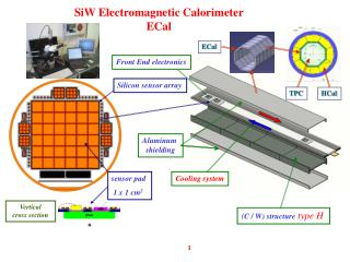
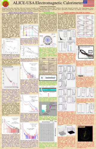
Requirements for ECAL0 1. The geometrical size is ~ 2.0 - 2.5 m2 with a central hole ~ 0.4 - 0.8 m2 and the total length (thickness) of the calorimeter should be of about 50 cm. 2. Located downstream of RPD. ECAL0 should cover the polar angular range 0.15-0.6 Rad. 3. A modular structure. 4. Energy resolution ≤ 10.0%/√E (GeV) or better. 5. The photodetector should be insensitive to the magnetic field. R&D of ECAL0 prototype was being performed in 2008-2011 Final prototype had been tested in 2011. 7 - 13 July SPIN-Praha-2013
ECAL0 in the COMPASS setup 7 - 13 July SPIN-Praha-2013
“Shashlyk”-type calorimeter module for ECAL0 7 - 13 July SPIN-Praha-2013
Micropixel Avalanche PhotoDiodes – MAPD Surface-pixellated structure Deep micro-well structure 2011 year • Pixels are on the surface • Gain is up to 106 • Has pixel density ~ 102 - 103 mm-2 • PDE is up to 40% (100 mm-2) • PDE depends on pixel density (decrease with increasing density) • Small dynamic range (depends on total number of pixels) • Typical pixel size is (25-100)x(25-100) µm • Pixels are deep inside epitaxial layer • Gain is up to 105 • Has pixel density ~ 104 mm-2 (up to 40 000 mm-2) • PDE is up to 30% (15 000 mm-2) • PDE slightly depends on pixel density (decrease with increasing density) • Large dynamic range (depends on total number of pixels) • Typical pixel size is (2-5)x(2-5) µm 7 - 13 July SPIN-Praha-2013
Results of beam tests for 3x3 modules prototype 7 - 13 July SPIN-Praha-2013
Modules mass-production Institute for Scintillation Materials, Kharkov, Ukraine is playing major role in calorimeter production by JINR design (lead and sci plates, assembling, fiber insertion, pretests, etc) • Joint Institute for Nuclear Research is responsible for: • - Has organized and is managing production in Kharkov • MAPD production (from Zecotek’s wafers) and tests • Photodetector unit production and tests • Tests of final modules, cosmic tests • Beam tests and investigation of modules injection-molding of scintillation plates Painting scintillation plates Prober setup for wafer tests Intermediate tests and studies of electronics, MAPD, photodetector units, etc Assembling calorimeters Cosmic tests of modules Wafer of MAPD-3N chips Production of photodetector units MAPD casing procedure General view of assembled calorimeter module 7 - 13 July SPIN-Praha-2013
Installation and commissioning • Aluminium frame filled with 56 modules • ECAL0 tests with cosmics performed in assembly zone (COMPASS DAQ used) • ECAL0 craned into final position in spectrometer • Air cooling installation • Power supplies(Bias voltage)&Thermostabization &monitoring(LED) elements were developed by HVSYS company (Dubna) The first fragment of the ECAL0 consisting of 56 modules was made for 2012 Run. 7 - 13 July SPIN-Praha-2013
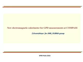
Conditions The first part of ECAL0 installed in COMPASS was successfully prepared for 2012 GPD pilot run data taking and operated well during October-December. Figures show beam load over ECAL0, MAPD amplitude variation and temperature inside the ECAL0 box. The temperature stabilization system operating in a range 15-25 °C . MAPD temperature is maintained with an accuracy < 0.1 °C 7 - 13 July SPIN-Praha-2013
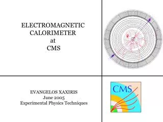
ECAL0 Intercalibration October 12, 2013 ECAL0 calibration with muon beam For ECAL0 module deposited fraction energy e/γ Eactive ~16%, 1 GeV e/γ -> 160 MeV Energy deposition from muon at 160 GeV -> 34.3 MeV in cell -> muon peak corresponds to 214 MeV All channels were roughly settled in according to this procedure. Calibration energy coefficient correction based on LED_in_spill / LED_out_of_spill. This correction is different muon/pion beams due to different backgrounds. Muon beam -> average ~1.65% Pion beam-> 4.75% Muon peak in different towers Nonlinearity of MAPD response at 5GeV was measured to be about 5% and it also can be taken into account on the cluster reconstruction level. Correction coefficients distribution for 504 towers. Muon beam (top), Pion beam (bottom) 7 - 13 July SPIN-Praha-2013
Long-term stability of FEM-system FEM LED stability studies. FEM#1÷4 stability over 1 month: November1 – Novenmber30, 2013 4 PIN-photodiodes for LED light monitoring were used Monitoring system consist of 4 Light sources. Each source supplied quarter of ECAL0-prototype channels via light distributor 1 -> 16 LEDs amplitudes variations < 1% 7 - 13 July SPIN-Praha-2013
Long-term stability of ECAL0 MAPD response stability over 1 month: November1 – Novenmber30, 2013 MAPDs amplitudes variations ≈ 1% cell# X=15 Y=1 cell# X=15 Y=4 over all cells cell# X=15 Y=22 cell# X=4 Y=13 cell# X=15 Y=25 cell# X=31 Y=13 cell# X=28 Y=13 cell# X=1 Y=13 7 - 13 July SPIN-Praha-2013
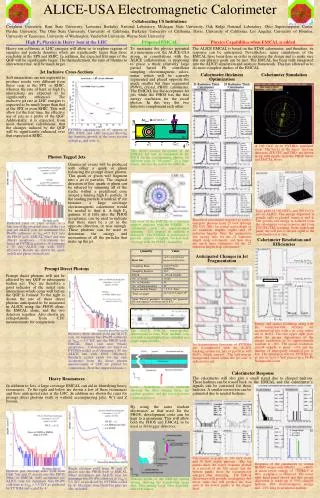
Results Cluster reconstruction • Cluster position -position of a central cell • Cluster energy -sum of energy deposition in 9 (3x3) cells • Cluster position -position of a central cell • Cluster energy -sum of energy deposition in 9 (3x3) cells All cells Peak width is 12% ~8% -resolution of 1 cell ~8% -cell-to-cell misalignment Intercalibration of each of the ECAL0 cells with muon halo provides precision about 8% MIP signal obtained in inter-calibration with muon halo (all cells together). Physical calibration: • π-beam of 190 GeV/c with intensity 0.5 106 s-1 • LH target • Special ECAL0-based trigger was developed. • ECAL0 based trigger: total energy deposition in ECAL0 >6GeV (3 GeV) • Working tracking for primary vertex reconstruction • Final calibration constants were obtained by moving π0 mass peak to it’s nominal position π0 peak in γγ mass spectrum obtained in calibration with pion beam. (π0 mass is subtracted in X-axis) Physical data sample collected with muon beam demonstrates well-visible π0 peak in γγ mass spectrum. Its position is shifted from the nominal because precise π0 calibration was not used yet for production of the data. The time resolution of cluster depends on cluster energy and for energy above 1GeV is less 1 ns γγ mass spectrum for semi- inclusive muon events (π0 calibration is not applied yet). π0 peak =127.2 MeV
Summary Part (56 modules) of ECAL0 for 2012 DVCS PILOT RUN built up and put into operation. It demonstrated good performance: E and T resolutions, linearity and stability fully correspond to expectations. The signal from π0 decays was seen in ECAL0 Data for calibration with π- was taken and are being used. The full scale ECAL0 is under production. 200 modules will be produced at ISMA (Kharkov, Ukraine) till the end of this year. We are going to produce Registration Units as soon as we get new batch of photodiodes. Beam tests in Bonn at ELSA: studying angular dependences The design of the ECAL0 modules is could be used for the NICA/SPD ECAL. 7 - 13 July SPIN-Praha-2013