Download
1 / 15
150 likes | 262 Views
LQX Engineering Design Review Introduction Jim Kerby 12 March 2001. Scope Requirements Interfaces. Scope. To IP . pipes*. pipes. pipes. pipes. MCBXA. MQXA. MQSXA. MCBX. MQXA. MQXB. MCBX. MQXB. TAS. BPM. TAS. BPM. C /W. beam tube. beam tube. beam tube. beam tube.

E N D
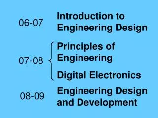
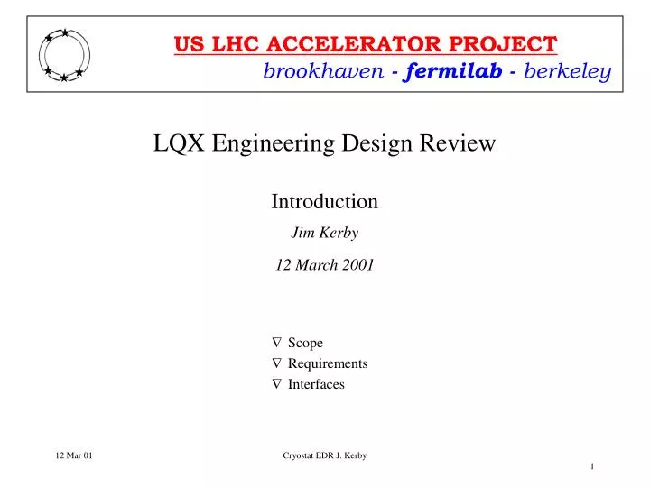
LQX Engineering Design ReviewIntroductionJim Kerby12 March 2001 • Scope • Requirements • Interfaces Cryostat EDR J. Kerby
Scope To IP pipes* pipes pipes pipes MCBXA MQXA MQSXA MCBX MQXA MQXB MCBX MQXB TAS BPM TAS BPM C /W beam tube beam tube beam tube beam tube LMQXB LMQXA LMQXC LQXB LQXA LQXC IK 3 IK 2 IK 1 IK 4 “Q3” “Q1” “Q2” KEK supplied CERN supplied FNAL supplied • Interconnect kits (IK) and beam tube liners installed at CERN • IP 2/8 interconnect kits do not have TAS components Cryostat EDR J. Kerby
Requirements • Derived from Inner Triplet and Main Component Interfaces • Optics / Layout • Alignment • Heat Load / Cryogenic • Radiation • Electrical • Mechanical Cryostat EDR J. Kerby
Optics / Layout • The optics / layout is based on v6.2 optics • recent discussions on moving Q2 further from the IP and relocating a BPM are not reflected in these presentations • the impact can be discussed later this afternoon Cryostat EDR J. Kerby
Alignment • Inner Triplet Alignment Table defines overall requirements • Q2a/Q2b assembly mechanical tests completed last year • Use of the Stretched Wire measurement system makes cryostat mechanical tolerances internal, and no build up of tolerances occurs • Positioning of the lugs is directly related to allowable bellows offset Cryostat EDR J. Kerby
Cryogenics • The dynamic heat load of the inner triplet is much higher than in the arcs • 6 W/m to 1.9K (avg) • Cryostat static heat load a less critical parameter • Heat Exchanger system designed and tested to effectively cool for these loads Q1 (51W) Q2a (27W) Q2b (50W) Q3 (43W) Cryostat EDR J. Kerby
Cryogenics • Cryostat includes all piping for all cryogenic loops • All Cryostat assemblies include the piping required for location in any of the eight locations • 4.5K loops left open in IP2/8 • Liquid feed line added in uphill installations through heat exchanger • Feed and return lines included and connected depending on exact location in tunnel • All loops routed to DFBX Cryostat EDR J. Kerby
Radiation • Deposition studies also give radiation environment • MQXB and MQXA cold masses are limited to 6-7 years at nominal luminosity in LHC inner triplets • The peak calculated load to the cryostat components is 13.5kGy / year Cryostat EDR J. Kerby
Electrical • Quads provide route for all bus and wire internal to the helium vessel • BPM leads, passive heater instrumentation routed out locally through vacuum vessel Cryostat EDR J. Kerby
Electrical • All buss and wire in the magnets are routed back to the DFBX Main and Corrector buss routed through lower slots in magnet Expansion loops go around correctors Instrumentation wires through side slots Cryostat EDR J. Kerby
Mechanical • Mechanical interfaces within the LQX are well understood • Mechanical drawings of Fermilab, KEK, and CERN magnets are circulated and discussed thoroughly. All production drawings are OK. • Discussions on the lengths and locations of leads have recently converged • Means to transfer the magnetic alignment information for each magnet are defined and reflected in the drawings • Cryostat interface to supports is known • Alignment transfer gallery interface has been defined • Interconnect Kits are impacted by the current discussions on BPM location, TAS design, and active/passive beam tube liners and therefore are not as yet converged. Cryostat EDR J. Kerby
Mechanical • MQXA... Cryostat EDR J. Kerby
Mechanical • MQXB... Cryostat EDR J. Kerby
Mechanical • MCBX... Cryostat EDR J. Kerby
Mechanical • MQSXA... Cryostat EDR J. Kerby