Download
1 / 41
410 likes | 502 Views
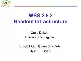
WBS 2.6.3 Readout Infrastructure. Craig Dukes University of Virginia Bill Gilbert University of Minnesota CD2/3a DOE Review of NO u A October 23-25, 2007. Organization. Power Distribution System (PDS) (Dukes) APD Thermoelectric Cooler Cooling System (Gilbert).

E N D
WBS 2.6.3Readout Infrastructure Craig Dukes University of Virginia Bill Gilbert University of Minnesota CD2/3a DOE Review of NOuA October 23-25, 2007
Organization • Power Distribution System (PDS) (Dukes) • APD Thermoelectric Cooler Cooling System (Gilbert) • 2.6.3.1 Low voltage power supplies/racks • 2.6.3.2 High voltage power supplies • 2.6.3.3 Power cables/cable trays • 2.6.3.4 Power distribution boxes (PDBs) • 2.6.3.5 Cooling • 2.6.3.6 Shipping WBS Items Craig Dukes, Nicole Fields, Emmanuel Munyangabe, Yoshihiro Masui, Andrew Norman University of Virginia Bill Gilbert, Roger Rusak University of Minnesota Leon Mualem Caltech Dukes/Gilbert/WBS 2.6.3
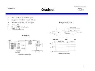
Power Distribution System • Feeds electrical power to: • The Avalanche Photodiodes (APDs) • The Thermoelectric Coolers (TECs) • The Front End Boards (FEBs) • The Data Concentrator Modules (DCMs) • Requirements • Low noise (3.3V + 450V) • Remote control and monitoring • Floating power supplies • Remote sensing for LV supplies • Reliable operation over 10+ years Dukes/Gilbert/WBS 2.6.3
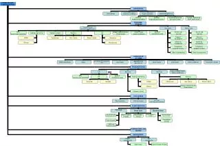
Power Distribution System Layout Dukes/Gilbert/WBS 2.6.3
PDS Power Requirements Dukes/Gilbert/WBS 2.6.3
Far Detector Di-block Layout Dukes/Gilbert/WBS 2.6.3
Near Detector Layout Dukes/Gilbert/WBS 2.6.3
IPND Layout Dukes/Gilbert/WBS 2.6.3
Electronics Counts Dukes/Gilbert/WBS 2.6.3
High Voltage Supply • CAEN SY1527LC mainframe • CAEN A1511B card • 12 ch, 0-500 V, 15 mA • Individually floating channels • Voltage resolution: 100 mV (~0.5%) • Ripple: < 30 mV pp • Each channel serves 2 PDBs • Only 1 mainframe needed for entire FD • Ethernet (TCP/IP) interface • Widely used at Fermilab Dukes/Gilbert/WBS 2.6.3
Low Voltage Supply • Wiener PL508 System • Floating • Remote sense • 3 3.3V pods, 3 24V pods → each MF feeds 3 PDBs → 66 MFs needed • Ripple: < 3 mV pp • Ethernet (TCP/IP) interface • Widely used at Fermilab Dukes/Gilbert/WBS 2.6.3
Power Distribution Box • Fans out 3.3V, 24V, and 450V to up to 64 FEB boards, and 24V to 1 DCM • 3U crate • 16 x 4 + 2 = 66 FEB channels • LED indicators for crate 3.3V, 24V, and 450V power • LED indicators for card 3.3V and 24V power • Front panel on/off switches • Fused with TVS for 3.3V lines • Note: FEBs have voltage regulators • Reference to ground • Designed and built at UVa • FD: 198 • ND: 10 Dukes/Gilbert/WBS 2.6.3
Prototype PDB Fabricated • Works according to specifications • Minor redesign in progress (mainly to simplify construction) Dukes/Gilbert/WBS 2.6.3
Mounting the PDS on the Far Detector Dukes/Gilbert/WBS 2.6.3
Cables • All cables “tray cable” • Oil resistant jackets Power Supply to PDB Dukes/Gilbert/WBS 2.6.3
Cable Safety Power supply to PDB cables can handle full current capacity of power supplies. PDB-FEB 4A max Wiener-FEB 24V: 23A max Wiener-FEB 3.3V: 110A max Dukes/Gilbert/WBS 2.6.3
Power Budget and Voltage Drops Dukes/Gilbert/WBS 2.6.3
Cable Trays Dukes/Gilbert/WBS 2.6.3
Detector Cooling Overview • 17 air breathing 2 ton chillers located on upper walkway • Each chiller serves 2 detector blocks • Started one at a time to reduce peak electrical and heat load Detector Top View 17 chillers Steady state heat load to air per chiller: Heat from APD/TE modules 3.35w x 744 = 2492w Heat from chiller operation (33% capacity) + 2310w Net* heat load to air per chiller = 4802w Net* total heat rejected to air by 17 units = 82 kw *Ignores pipe & tube loading, gained from air, rejected to air, approx 2.3 kw per chiller Dukes/Gilbert/WBS 2.6.3
Water Distribution Scheme prefabricated distribution manifolds prefabricated hose manifolds Dukes/Gilbert/WBS 2.6.3
Hose Manifold Section • With single-sided detector readout, all manifolds are identical, 32 hose style. • Two piece construction eases shipping and handling distribution manifold 1.25” compression couplings Cap 3/4”Sch 120 plastic pipe 1/8” I.D. hoses with valved disconnect 175 cm overall length 350 cm Dukes/Gilbert/WBS 2.6.3
Prototype Hose Manifold Shown with pipe insulation, will be tested with & without insulation Dukes/Gilbert/WBS 2.6.3
Distribution Manifold Section union couplings 1.25” plastic pipe Expansion joint, 6.75cm range, handles exp/contr and dimensional tolerances ball valves 3/4” pipe taps 116cm 131cm 15cm 262 cm (8.6 ft) +/- 3.37cm Return Pipe Section Dukes/Gilbert/WBS 2.6.3
Water Schematic Far Detector Dukes/Gilbert/WBS 2.6.3
Water Schematic IPND 310 APD Modules Total 9.8 GPM, 1.04 kW 2 APD rows detector top Chiller Sensor Panel Each manifold serves 31 APD modules 3 APD rows detector side Dukes/Gilbert/WBS 2.6.3
Water Schematic Near Detector Dukes/Gilbert/WBS 2.6.3
Water System Pressures Working pressure and worst case pressure is well under design pressure of 100 PSI Dukes/Gilbert/WBS 2.6.3
Chiller Control & Instrumentation DCS monitors cooling system, can adjust water temp, and start/stop chillers Dukes/Gilbert/WBS 2.6.3
Flow Network Modeling Cooling system design is being modeled using: http://www.inres.com/Products/MacroFlow_Electronic/macroflow_electronic.html Dukes/Gilbert/WBS 2.6.3
Hose/Heatsink Net Model Dukes/Gilbert/WBS 2.6.3
Hose Assy Diff Pressures Drilled orifices in hose barbs are the dominant restriction governing flow Changes in hose length or heatsink resistance will not be significant Dukes/Gilbert/WBS 2.6.3
Hose Manifold Network Model Dukes/Gilbert/WBS 2.6.3
Hose Manifold Temp Uniformity Total Spread = 0.15 DegC Dukes/Gilbert/WBS 2.6.3
Hose Manifold Flow Uniformity Excellent uniformity is due to large relative diameter (0.690 in) of manifold pipe Dukes/Gilbert/WBS 2.6.3
Distribution Network Model Dukes/Gilbert/WBS 2.6.3
Distribution Flow Balance Flow balance will not be disturbed by minor modifications to supply piping Flow can be adjusted using one valve near chiller without affecting balance Use of 0.040 orifices in hose barbs creates inherent balance Detector Top Detector Side Dukes/Gilbert/WBS 2.6.3
Distribution Temp Uniformity Detector Top Detector Side Total Spread = 0.06 DegC Dukes/Gilbert/WBS 2.6.3
Testing the Cooling Model • Two key model elements will be tested: • Hose/heatsink assembly flow and pressure characteristics will be measured with various orifice sizes • Prototype manifold pair with hose assemblies will be tested for ambient heat gain and temperature uniformity • Details: • Chiller will provide 15 DegC water at 64 mL/s • 4 hose/heatsink assemblies along manifold will be instrumented with thermistors • Input & output water temperatures measured with thermistors • Overall flow rate measured with rotameter, controlled with valve • Input & output pressures measured with transducers • Temp & pressure recorded using data logger and computer Dukes/Gilbert/WBS 2.6.3
Costs (ND+FD) Dukes/Gilbert/WBS 2.6.3
Procurement • Power Distribution System • Power supplies to be bought and shipped to Virginia to be tested. • Cables will be cut, terminated and tested at Virginia. • Power Distribution Boxes will be fabricated and tested at Virginia. • Cable trays and relay racks will be delivered directly to the Far Detector site and FNAL. • Cooling System • Manifolds will be fabricated and shipped by vendor to the Far Detector site and FNAL on a di-block by di-block basis. • Chillers and cooling interface panels will be ordered and shipped by vendor to Far Detector and FNAL. Installation in WBS 2.9.4 Dukes/Gilbert/WBS 2.6.3
Schedule • Lots of float: no critical-path items! • Power Distribution System • Fabrication of PDBs: • Need 215, including spares. Make and test 1/day with 1 tech • 200 days/1 tech • Fabrication of cables: • Dominated by 12,000 PDB-FEB cables: • 1 student: cut, terminate, pack 5 cables/h: 80 days/4 undergrads • Will do it in summer of 2010 with student labor • UVa HEP building has enough storage for complete system → will deliver to detector in 3 shipments • Cooling System • Vendors can deliver as needed to keep up with outfitting schedule Dukes/Gilbert/WBS 2.6.3