Download
1 / 30
300 likes | 401 Views
The Design and Implementation of BESIII EMC Trigger System. Qiao Qiao 2006-1-10. Outline. Introduction Trigger condition The hardware design of EMC Trigger System Module details. Introduction.

E N D
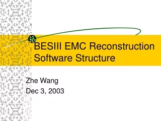
The Design and Implementation of BESIII EMC Trigger System Qiao Qiao 2006-1-10
Outline • Introduction • Trigger condition • The hardware design of EMC Trigger System • Module details
Introduction • The Electromagnetic Calorimeter (EMC) comprises of = 44120= 5280CsI crystals in barrel, 960 crystals in endcaps, which is used to detect photons and electrons, to select Bhabha events and pure neutral events.
BESIII EMC Trigger System has two ways to pick out good events . One is based on the position and counts of the cluster, the other is based on the position of the energy block and the total energy deposition in the EMC.
Trigger condition • Trigger cell. • The trigger condition from the trigger clusters. • The trigger condition for energy selection.
Trigger cell 1、size and threshold: • 4*4 crystals make up a trigger cell in the barrel while in the endcap this number changes to 15 or 16 • TC threshold is chosen as 60-80Mev . 2、the rising-edge of the over-threshold signal contains the timing information of the TC. 3、In order to pick out real, isolated clusters, the cluster isolating algorithm must be applied to all the neighboring Clusters.
BEMC:use 3*3 TCs to pick out the isolated clusters according to ‘the most right and top’ rule. For example , to judge the NO.0 TC, NO.0 must be ‘hit’,NO.1 and NO.3 can’t be ‘hit’ ,NO.4 and NO.8 can’t be ‘hit’ together. • EEMC: each endcap has 32 TCs ,which are later transformed into 16 big TCs. For example ,NO.0 and NO.1 are big TCS, to judge the NO.0 TC, NO.0 must be ‘hit’ and NO.1 can’t be ‘hit’.
WCLS1 ECLS1 西 WCLS9 东 ECLS9 The trigger condition from the trigger clusters 1、The clusters in the barrel Nclus >=1, Nclus >=2. 2、’Back to Back’ condition in the barrel and endcap. (BclusBB,EclusBB) • Barrel: One cluster corresponds to 3*5 (Z)clusters in the opposite position. • Endcap: One cluster corresponds to 3 clusters in the opposite position.
Clus_PHI WCLS1 ECLS1 西 东 WCLS9 ECLS9 3、Cluster balance in direction: • Barrel: TCs in the same direction are organized into 30 cell strips using the method of logic “or”. One cell strip corresponds to 15 cell strips in the opposite position. • Endcap: One big TC corresponds to 7 TCs in the opposite position. -------balance of the barrel “||” balance of the endcap == Clus_PHI. 4、Cluster balance in z direction: • Both sides should have an isolated cluster at the same time.
The trigger condition for energy selection • 12 energy blocks for barrel , EB1-EB6(EAST),WB1-WB6(WEST). • 4 energy blocks for endcap, EEB1,EEB2,WEB1,WEB2. 1、Energy threshold : the high threshold for the total energy deposition in the barrel (BEtot_H )and in the endcap (Eetot_H) is 2.3Gev. 2、The middle threshold for the total energy deposition(Etot_M) is 700Mev and the low threshold for the total energy deposition (Etot_L) is 200Mev. 3、Energy balance in z direction (BL_Z ). 4、Differential energy balance in z direction (Diff_B and Diff-E). 5、 Energy block balance(BL_BLK). 6、 Endcap energy balance in z direction (BL_EEMC).
Comparing the sum of the energy deposition both in barrel and endcap with the corresponding threshold and create the energy trigger condition . Process the block energy to get the balance condition of energy. • comparing the TC energy with the energy threshold for the cluster counting, picking out the time information of the EMC ,adding the TC energy to the block energy. The hardware design threshold comparator Energy block balance Energy condition Add up to the energy block FADC fiber threshold Total energy ETOT Pick out the timing information Receive analog signal Locate the cluster position Shaping Of the TC fiber Judging cluster Cluster condition TCBA Count the cluster the Read-in and arrangement of the TC, pick out the isolated clusters using the cluster isolating algorithm , create some trigger condition such as cluster counting ,’back to back’, and so on. TC adding CSUM Cluster distributing
TCBA module: comparing the TC energy with the energy threshold for the cluster counting, picking out the time information of the EMC ,adding the TC energy to the block energy. • CSUM module: the Read-in and arrangement of the TC, pick out the isolated clusters using the cluster isolating algorithm , create some trigger condition such as cluster counting ,’back to back’, and so on. • ETOT module: Comparing the sum of the energy deposition both in barrel and endcap with the corresponding threshold and create the energy trigger condition . Process the block energy to get the balance condition of energy. • TCBAT module: create the test signals for the TCBA module . 30 channel LVDS signals ,L1, TSYNC, FRST, RST and CLK signals.
Module Detail • TCBA module:
1、Timing circuit. • Abundant time information exists in the detector output signals. • The performance of the signals from the preamplifier: • Maxim amplitude : 2V • Gain uniformity : 20% • Shaping parameter uniformity: 20% • Peak time: 1 s • When the amplitude and peak time of the input signals change, time jitter should be small.
We need to find the zero crossing time, which is difficult to confirm. That’s why a proper threshold might play an important role here. Low might be good but too low will cause noise trouble. • Case 1: the signal amplitude changes, here P1,P2. (T2-T1) is the time jitter. • Case 2: the signal peak time changes, here P1,P3. (T3-T1)is the time jitter.
we use two ways on the test board comparing with each other. • Zero crossing timing • Leading edge timing • As a result , leading edge timing is better.
2、TCs Energy adding circuit. • We add up the 30 channel TCs energy to the block energy by two amplifier layers. • A FADC is needed to convert the block energy to digital signal. • The digital energy signal is divided into two parts, one is transmitted through fiber after parallel-to-serial conversion. The other is partly stored in FPGA for testing later.
3、FPGA: • To receive the digital output signals of FADC and discriminator. Working at normal mode ,FPGA just send the data to TLK1501(parallel-to-serial). While at test mode, FPGA can read, write, and interrupt through VME bus. • The interrupt service allows the vme bus to read out the data saved in FPGA RAM in the “BLOCK READ” way, through which we can get the data to recover the analog block energy signal and get the relative time jitter. The recovered analog signal
All the above is for the primary function of TCBA module. • In the second version, an analog switch is added to eliminate the noise .When the signal crosses this threshold , the switch is turned on, then the signal is allowed to go into the adding circuit. • In the third version, we use ROCKETIO mode instead of TLK1501 to do parallel-to-serial conversion. Monostable multivibrator is used to stretch and delay the discriminated signals .(In the first two version, this is done in FPGA.) Then the ‘and’ signals are converted from TTL to LVDS, then to FPGA. The LVDS signal level is lower than TTL , which can reduce the cross-talk interference. version 1 and version 2 has already been finished and PCB of version 3 is also ready now.
Csum module 12 barrel TCBA boards and 4 encap TCBA boards
1、Array the discriminated signals received from TCBA. The barrel data is reconstructed to a diagram and the endcap data is stored in two 32-bit registers.
0:final signal 0 1 2 3 4 5 6 7 8 9 10 11 12 0 2 6 8 7 1 3 5 9 10 11 4 & 12 5 1 6 0 2 3 5 6 8 9 11 12 1 4 7 10 2 3 0 + & 5 6 8 9 11 12 4 7 10 7 8 4 0 3 4 1 8 8 10 11 12 9 1 7 0 2 3 4 5 9 10 11 6 8 S0 register 1 7 0 2 3 4 5 9 10 11 6 8 S1 register( over S0) / 1 7 2 3 4 5 9 10 11 6 8 S3 register( S0 left shift) 1 7 0 2 3 4 5 9 10 11 6 8 S4 register( below S0) / 1 7 2 3 4 5 9 10 11 6 8 S8 register( S4 left shift) S1 S0 2、Cluster isolating algorithm. • TC 0(6 of line 3) is determined by TC 0 ,TC 1(6 of line 2), TC 3( 7 of line 3) , TC 4 (6 of line 4) and TC 8( 7 of line 4). S0(final)=S0&(not(S1+ S3))&(not (S4·S8)) S4
3、Trigger condition: • Different algorithm creates different condition . it’s impossible to introduce all kinds of algorithm, so I just want to introduce the algorithm of BCLUSBB. BCLUSBB Nclus1 & Nclus2 CLUS_Z ECLUSBB CLUS_PHI_B CLUS_PHI_E CLUS_PHI
0 1 2 3 4 5 6 7 8 9 10 11 11 2 4 5 6 3 1 0 10 9 8 7 • BCLUSBB:( ‘back-to-back’ condition of barrel) • Firstly, a reverse is taken from line NO.0 to NO.14. • Secondly , after ‘and’ method is applied among line NO.15 to NO.29, which means it is used for one TC ‘and’ the 15 corresponding neighboring TCs , the logics are stored to their original position. • Finally, a new planar table is created.
use the formula below to get the BCLUSBB condition. • If (R0N and R15OR) + (R1Nand R16OR) + …… + (R13N and R28OR) + (R14N and R29OR) is ”000000000000” ,BCLUSBB is ‘0’, else BCLUSBB is ‘1’.
4、FPGA on-line configuration: • VME can read ,write ,erase and reset the FLASH Memory by CPLD . • After Power-On, the configuration data in Flash Memory will be configured into FPGA by CPLD. • If VME gives a reconfiguration signal, the data in Flash Memory can be reconfigured into FPGA. • VME can also reconfigure FPGA by CPLD without Flash Memory.
We are debugging the CSUM version 1 now. • The ETOT is still in design and to be implemented. We are going to use the same PCB as CSUM.
TCBAT module( test board for TCBA) • The output analog signal is from DAC, which is controlled by FPGA. • The amplitude of the output signal is controlled by the digital potentiometer. • The output is 32-channel LVDS signal and L1,TSYNC,FRST,RST and CLK signals.
This module has been finished. • The diagram below is the waveform of the output signal. DS0 LVDS LEVEL OUTPUT SIGNAL