Download
1 / 43
430 likes | 531 Views
Sub-meV optics for medium energy X-ray spectroscopy: Principles and preliminary studies. XianRong Huang Advanced Photon Source, Argonne National Laboratory xrhuang@aps.anl.gov. Angular dispersion optics using grazing backscattering Multi-cavity Fabry-Perot

E N D
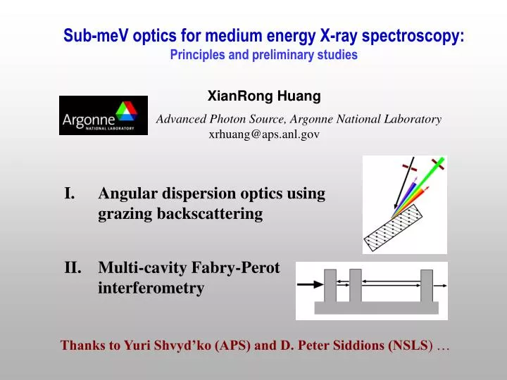
Sub-meV optics for medium energy X-ray spectroscopy: Principles and preliminary studies XianRong Huang Advanced Photon Source, Argonne National Laboratory xrhuang@aps.anl.gov Angular dispersion optics using grazing backscattering Multi-cavity Fabry-Perot interferometry Thanks to Yuri Shvyd’ko (APS) and D. Peter Siddions (NSLS) …
Sub-meV-resolution optics at medium energy (5-10 keV) • Inelastic X-ray Scattering (IXS): • Higher energy transfer resolution • Higher momentum transfer resolution, filling the gap between • high and low frequency probes • Higher brightness at medium energy for many synchrotrons, • particularly for NSLS-II • For ~1 nm focusing, may also need narrow energy bandwidths • Coherent imaging (coherent length = 2/) • High resolution X-ray diffraction • …
Toellner et al, APL71, 2112 (1997). E = 14.4 keV, E = 0.8 meV Acceptance 8.6 rad • High energy resolution optics: • Monochromator • Analyzer • … • based on single-crystal diffraction • Backscattering has the highest resolution: • FWHM 1meV for E 20 keV • but FWHM > 30 meV for E < 10 keV • Overall, FWHM when E • Even ~1 meV mono/analyzer for E <10 keV not realized yet! • For E >10 keV, 1 0.1 meV possible using multi-crystal diffraction, butsmall angular acceptance, a few rad, so NOT for analyzers! E = 14.4 keV, E ~ 0.1meV!!! Acceptance 6.4 rad Yabashi et al, Rev. Sci. Instrum. 72, 4080 (2001) How about <10 keV???
I. Angular dispersion optics using grazing back diffraction Goals: Sub-meV at E < 10 keV with wide angular acceptance Applicable for both Mono and Analyzer Shvyd’ko’s designs PRL97, 235502 (2006); NSLS-II Optics does not depend on Darwin Curve Width Backward CDS geometry In-line (forward) CDDS geometry
White incidence Polychromatic Refraction-based Dispersion of light by prism: Incident white light decomposed into component colors. Red light refracted less than violet, so propagating in different directions. Diffraction-based X-ray dispersion In asymmetric x-ray diffraction, the crystal is a natural “prism”.
Conservation of tangential momentum Relationship between wavelength and incident/exit angles Bragg law: Kh K0 + h
DuMond diagram S. Brauer et al. JSR2, 163 (1995) Angular dispersion in asymmetric diffraction No dispersion in symmetric reflection ( = 0 e ) = const Dispersion coefficient increases with e 0, grazing-exit geometry
Grazing backscattering e where To maximize resolution: 90°, e 0 A geometry effect Independent of the Structure Factors and Darwin curve, so also applicable to higher energy optics!
90° For Si 008 reflection: EH 9.1 KeV If angular acceptance of selectore = 5106 rad = 88.5 E = 0.6 meV = 89.6 E = 0.16 meV for a single dispersing crystal We can use (1) two dispersing crystals (described later) or (2) reduce e or (3) further increase (but must not exceed the critical angle ~89.8°) to achieve 0.1 meV!
Transmission through the thin crystal due to Bormann effect Si 008 Angular acceptance ~ 5 rad 2 0.6 meV Si 220, B = 20.7 Asymmetric factor |b| 20 Acceptance ~100 rad 5rad divergence of diffracted D C S CDS scheme CDS scheme DuMond Diagram Shvyd’ko et al., PRL97, 235502 (2006)
R(E,1) Si 220, B = 20.7 Full calculation using dynamical theory Total reflectivity R(E,1) = R1(E,1)T2(E,2)R3(E,3)R4(E,4)
= 88.5 E = 0.6 meV = 89.6 E = 0.16 meV Predicted Calculated with 1 =const Back diffraction reflectivity ~ 90% for 89.79º, close to the critical angle!!! Because b -1.
1 = 89.6° Angular acceptance ~ 87 rad > 100 rad for = 88.5°
Energy Tuning Selector fixed
Energy tuning Tuning rate 0.07 meV/rad
In-line (forward) CDDS scheme for a single dispersion crystal Resolution doubled for two D-crystals
Backward CDS steep wing one side Full dynamical theory calculations Inline forward CDDS
Horizontal divergence? Conservation of tangential momentum To treat incidence deviated by a small angle in the horizontal plane, replace 2/ with (2/)cos = (2/)(1 2/2...) Modification negligible when < 1 mrad
Experimental verification = 88.5° Shvyd’ko et al., PRL97, 235502 (2006) Shvyd’ko et al., SRI 2007
X-ray transmission topographs of selector (thin crystal) on peak off peak X. R. Huang et al., to be published
Technical issues 1. Long dispersion crystal (segmented) • 0.1 meV, E/E ~ 10-8 d/d ~ 10-8 temperature stability and homogeneity ~1 mK Thermal coefficient of Si: 2.5610-6 K-1 • No bending of the entire long crystal, < 1rad How to mount? (gravity) • Surface roughness of long crystals? No strict requirement for the stability of the undulator beam
Alternative designs? sin80o = 0.985 sin89.6o =0.99997563 General CDS
Unfortunately! compared with 87rad for CDS Spectrum of General CDS for collimated incidence compared with 0.18 meV (59%) for CDS
Add another collimator C to increase acceptance by a factor b, say 30 But also increases crystal lengths by b !!! How to increase acceptance?
Cons: Acceptance > 100 rad • The long crystals not shortened (for mono, could be shortened) • Efficiency less than CDDS. Pros: • More flexible, many variants • Avoid multi-beam diffraction • Arbitrary energy • Scan in wide energy range • More suitable for monos! More work is undergoing to optimize and to shorten the crystals
C2 D C1 S Yabashi et al, E = 14.4 keV, E ~ 0.1meV!!!
Conclusion of Angular Dispersion Optics • Sub-meV resolution optics ~ 0.1 meV with angular acceptance ~ 100 rad is feasible based on the Angular Dispersion Principle in asymmetric x-ray diffraction, no doubt in principles. • Backward CDS • In-line forward CDDS • Both using grazing back diffraction: E/E independent of E or Bragg reflection. • The smaller the photon energy E the smaller is the bandpass E. • For a fixed E, E can be varied by changing (crystal lengths change though). • Efficiency R and the Acceptance almost constant (while changing ). • Multiple-crystal CCDS • For both monos and analyzer (combined with mirrors) • Long crystals, strain free, temperature, no bending, mounting
II. Multi-cavity Fabry-Perot Interferometer In optics, a Fabry-Pérot interferometer typically made of two parallel highly reflecting mirrors: Spectrum For normal incidence = 90º Free spectral rangeEd 0.5hc/tc FinesseF = Ed/E R1/2/(1R)
No large-angle X-ray mirrors! Using diffraction reflectivity, particularly back diffraction X-ray interferometer
Chang SL et al., PRL94, 174801 (2005) Shvyd’ko et al., PRL90, 013904 (2003). Experiments: Dynamical theory simulation Si (12 4 0), t = 70 m, tc = 520 m Dynamical theory
Tough requirement of pre-monochromator Solution: Increase Ed. Ed 0.5hc/tc by shrinking the cavity distance tc
tc decreased to 80 m from 520 m 5 meV pre-monochromator is practical, but spectrum is not clean (and E increased). Solution:to increaseFinesse? F = Ed/E R1/2/(1R) i.e. to increase R, but this is difficult
True solution: using two cavities (a) Two-cavity resonaotor. (b) t1 = 45 m t2 = 90 m tc = 81 m. (c) t1 = 60 m (R increased) t2 = 120 m tc = 81 m
How to further increase the energy resolution? Three-cavity interferometer Compact, single-component, tiny yet powerful
Angular acceptance t1 = 60 m t2 = 120 m tc = 81 m Physical size limited
Substantial undercut on the outside wall is largely corrected this time, without messing up the verticality of the inside wall. Note that we etched deeper than 100 microns. There is still some bowing near the corner of the structure, but there is a way to address that.
How to avoid Absorption & Multi-Diffraction? • Multi-cavity interferometers suffer absorption • Diamond • Low absorption • High reflectivity (very close to unity) • High Debye-Waller temperature • Hard, resistance to bending, strains • Fabrication??? • Sapphire:avoid multiple diffraction • more energy choices • quality concern

![Identification of Stereochemical Isomers of [Mo(CO) 4 (L) 2 ] by Infra-Red Spectroscopy](https://cdn2.slideserve.com/4500730/identification-of-stereochemical-isomers-of-mo-co-4-l-2-by-infra-red-spectroscopy-dt.jpg)