Download
1 / 54
650 likes | 1.04k Views
Chapter 3: Networking and Internetworking. Introduction Types of network Network principles Internet protocols Network case studies: Ethernet, wireless LAN and ATM Summary. Network performance measures l = length of signal path in communication medium (metres)

E N D
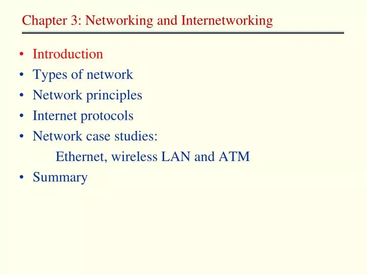
Chapter 3: Networking and Internetworking • Introduction • Types of network • Network principles • Internet protocols • Network case studies: Ethernet, wireless LAN and ATM • Summary
Network performance measures l = length of signal path in communication medium (metres) v = signal propagation speed in the medium (metres/second) L = average length of frame or packet (bits) C = transmission rate (bits/second) Propagation delay = l / v , in seconds shows how long a bit takes to propagate along the path Transmission time = L / C , in seconds shows how long it takes to get packet onto the medium Throughput: how fast data can pass a certain point can be measured in bits/second, packets/second, … Efficiency is related to throughput, e.g. efficiency = throughput (in packets/sec) * packet transmission time Revision on Networking
Consider an optical fibre 3000 km long with transmitter transmitting at 1.5 Gbps (1 Gbps = 1 000 000 000 bps). The signal propagation speed in optical fibre is approximately 200 000 km/sec. Suppose packet switching is being used with a packet length of 2000 bits. What is the bit propagation delay along the fibre ? What is the packet transmission time here ? How many packets have been transmitted and are propagating over the fibre when the first bit reaches the destination ? Ex1
Consider a route in a store-and-forward network going through 8 intermediate nodes. The packets contain 1000 bits and are transmitted at 64 kbps. Assume propagation delays over the links are negligible. As a packet travels along the route, it encounters an average of 5 packets when it arrives at each node. How long does it take for the packet to get to the receiver if the nodes transmit on a “first come first served” basis ? At each intermediate node, 6 packets must be transmitted in order for “our” packet to be transmitted: our packet finds 5 packets ahead of it, which will be transmitted first due to the “first come first served” policy. What is the bit propagation delay along the fibre ? What is the packet transmission time here ? How many packets have been transmitted and are propagating over the fibre when the first bit reaches the destination ? Ex2
150 nodes are connected to a 1000 metre length of coaxial cable. Using some (unspecified) protocol, each node can transmit 70 frames/second, where each frame is 1000 bits long. The transmission rate at each node is 100 Mbps. What is the per-node throughput ? What is the total throughput (of the 150 nodes) ? What is the efficiency of this protocol ? Ex3
Internetwork integrate many subnets that use different network technologies Requirements Unified internetwork addressing scheme that enables packets to be addressed to any host connected to any subnet A protocol defining the format of internetwork packets and giving rules according to which they are handled Interconnecting components that route packets to their destinations in terms of internetwork addresses, transmitting the packets using subnets with a variety of network technologies Internetworking
Internetworking • Internetwork • integrate many subnets that use different network technologies • Requirements • Unified internetwork addressing scheme that enables packets to be addressed to any host connected to any subnet • A protocol defining the format of internetwork packets and giving rules according to which they are handled • Interconnecting components that route packets to their destinations in terms of internetwork addresses, transmitting the packets using subnets with a variety of network technologies
Internetworking components • Router • Conduct routing, additionally link networks of different types • Bridge • link networks of different types, but not conduct routing • Hub • Connect hosts and extend segments of Ethernet and other broadcast local network • Switch • Perform similar function to router, but for LANs only
Chapter 3: Networking and Internetworking • Introduction • Types of network • Network principles • Internet protocols • Network case studies: Ethernet, wireless LAN and ATM • Summary
Internet protocols • Protocol layers (n1) • TCP(UDP)/IP,(n2) web [HTTP], Email [SMTP,POP], news [NNTP], FTP, SSL, etc • Exceptions to the universal adoption of TCP/IP • The use of WAP for wireless applications on portable devices • Special protocols to support multimedia streaming applications • Heterogeneous underlying networks support • The success of TCP/IP: independence of the underlying transmission technology (n3) • E.g., IP over ATM, IP over Ethernet, IP over PPP, etc
Message Layers Application Messages (UDP) or Streams (TCP) Transport UDP or TCP packets Internet IP datagrams Network interface Network-specific frames Underlying network Internet protocol layers
IP addressing • Schemes for naming and addressing hosts and for routing IP packets to their destination is challenging. • Requirement: • It must be universal • It must be efficient • The addressing scheme must lend itself to the development of routing scheme • The scheme • A 32-bit numeric identifier containing a network identifier and a host identifier • There are four allocated classed of Internet address-A,B,C,D
octet 1 octet 2 octet 3 Range of addresses Network ID Host ID 1.0.0.0 to Class A: 1 to 127 0 to 255 0 to 255 0 to 255 127.255.255.255 Network ID Host ID 128.0.0.0 to Class B: 128 to 191 0 to 255 0 to 255 0 to 255 191.255.255.255 Network ID Host ID 192.0.0.0 to Class C: 0 to 255 0 to 255 1 to 254 192 to 223 223.255.255.255 Multicast address Multicast address 224.0.0.0 to Class D (multicast): 224 to 239 0 to 255 0 to 255 1 to 254 239.255.255.255 240.0.0.0 to Class E (reserved): 240 to 255 0 to 255 0 to 255 1 to 254 255.255.255.255 Decimal representation of Internet addresses Two steps were taken: IPv6, Classless interdomain routing (CIDR)
IP protocol • Transmits datagrams from one host to another, if necessary via intermediate routers • Unreliable (best-effort) delivery semantics • packets can be lost, duplicated, delayed or delivered out of order • Address resolution: Address Resolution Module(ARP) • IP address -> Ethernet address mapping, (IP address, Ethernet address) pairs cache on each host
[1] Addressing • [1] How to find if destination is in the same network ? • IP address = network ID + host ID. • Source and destination network IDs match => same network (I.e. direct connectivity) • Splitting address into multiple parts is called hierarchical addressing Network Host Boundary
IP datagram: 223.1.1.1 223.1.2.1 E B A 223.1.1.2 source IP addr 223.1.2.9 misc fields dest IP addr 223.1.1.4 data 223.1.2.2 223.1.3.27 223.1.1.3 223.1.3.2 223.1.3.1 Dest. Net. next router Nhops 223.1.1 1 223.1.2 223.1.1.4 2 223.1.3 223.1.1.4 2 IP Forwarding: Example Scenario routing table in A datagram remains unchanged, as it travels source to destination addr fields of interest here
223.1.1.1 223.1.2.1 A E B 223.1.1.2 223.1.2.9 223.1.1.4 223.1.2.2 223.1.3.27 223.1.1.3 223.1.3.2 223.1.3.1 Dest. Net. next router Nhops 223.1.1 1 223.1.2 223.1.1.4 2 223.1.3 223.1.1.4 2 IP Forwarding (Direct) misc fields data 223.1.1.1 223.1.1.3 • Starting at A, given IP datagram addressed to B: • look up net. address of B • find B is on same net. as A • link layer will send datagram directly to B inside link-layer frame • B and A are directly connected
223.1.1.1 223.1.2.1 A E B 223.1.1.2 223.1.1.4 223.1.2.9 223.1.2.2 223.1.3.27 223.1.1.3 223.1.3.2 223.1.3.1 Dest. Net. next router Nhops 223.1.1 1 223.1.2 223.1.1.4 2 223.1.3 223.1.1.4 2 IP Forwarding (Indirect): Step 1 misc fields data 223.1.1.1 223.1.2.2 • Starting at A, dest. E: • look up network address of E • E on different network • A, E not directly attached • routing table: next hop router to E is 223.1.1.4 • link layer sends datagram to router 223.1.1.4 inside link-layer frame • datagram arrives at 223.1.1.4 • continued…..
Dest. next 223.1.1.1 network router Nhops interface 223.1.2.1 E B A 223.1.1 - 1 223.1.1.4 223.1.1.2 223.1.2 - 1 223.1.2.9 223.1.2.9 223.1.1.4 223.1.3 - 1 223.1.3.27 223.1.2.2 223.1.3.27 223.1.1.3 223.1.3.2 223.1.3.1 IP Forwarding (Indirect): Step 2 misc fields data 223.1.1.1 223.1.2.2 • Arriving at 223.1.1.4, destined for 223.1.2.2 • look up network address of E • E on same network as router’s interface 223.1.2.9 • router, E directly attached • link layer sends datagram to 223.1.2.2 inside link-layer frame via interface 223.1.2.9 • datagram arrives at 223.1.2.2
Host, router network layer functions: • ICMP protocol • error reporting • router “signaling” • IP protocol • addressing conventions • datagram format • packet handling conventions • Routing protocols • path selection • RIP, OSPF, BGP routing table The Internet Network layer Transport layer: TCP, UDP Network layer Link layer physical layer
IP address:32-bit identifier for host, router interface Interface: connection between host, router and physical link router’s typically have multiple interfaces host may have multiple interfaces IP addresses associated with interface, not host, router Hosts in the same network have same network ID 223.1.1.2 223.1.2.1 223.1.3.27 223.1.3.1 223.1.3.2 223.1.2.2 IP Addressing: introduction 223.1.1.1 223.1.2.9 223.1.1.4 223.1.1.3 223.1.1.1 = 11011111 00000001 00000001 00000001 223 1 1 1
IP Address Formats 0 Network Host 1 7 24 bits • Class A: • Class B: 10 Network Host 2 14 16 bits • Class C: 110 Network Host 3 21 8 bits • Class D: 1110 Multicast Group addresses 4 28 bits • Class E: Reserved. Router Router
Subnet Addressing • Classful addressing inefficient: Everyone wants class B addresses • Can we split class A, B addresses spaces and accommodate more networks ? • Need another level of hierarchy. Defined by “subnet mask”, which in general specifies the sets of bits belonging to the network address and host address respectively Network Host Boundary is flexible, and defined by subnet mask
IP routing • Routs packets from source to destination • Internet topology: Autonomous System, Areas(n1) • Routing algorithms: • RIP -1 • RIP-2 • Open Short Path First (OSPF) • Default routes: trade routing efficiency for table size • Classless interdomain routing (CIDR): create subnet by means of subdividing address or aggregating addresses by mask field, e.g. 162.105.203.0/24
Future of IP • IPv6(n1) • 2128 (3*1038) addresses, 1000 IP addresses per square meter of the Earth’s surface • Routing speed : no checksum, no fragmentation • Real time : priority and flow label which is used to reserve resources • Extension header ( information of router, authentication, etc), • multicast and anycast • Security through extension header type • Migration from IPv4: • IPv6 router island, • depend on economics
Sender Subsequent IP packets Mobile host MH tunnelled to FA Address of FA returned to sender First IP packet addressed to MH Internet Foreign agent FA Home First IP packet agent tunnelled to FA The MobileIP routing mechanism
TCP and UDP • Use of ports • Provide process-to-process communication • UDP features • TCP features
UDP features • Connectionless • Datagram delivery • A UDP datagram is encapsulated inside an IP packet, up to 64kb in size • Con • unreliable delivery due to unreliable IP • Pro • minimal additional cost and transmission delays
TCP • Connection oriented • two side must shake hands to establish a bi-directional communication channel • Message delivery • Deliver arbitrary long sequences of bytes via stream-based programming abstraction • Sequencing: divide stream into data segments, sequence number on each segment • Checksum: cover the header and the data in the segment • Flow control • Receiver send the highest number of received segment and window size to sender by acknowledge message • Buffering: receiver buffer and sender buffer used for flow control • In interactive application, receiver inform sender when timeout or the buffer reaches the MTU limit • Retransmission: retransmit the segment when no acknowledgement within a specified timeout
Domain names • Symbolic names for hosts and networks • upm.edu.my • The DNS would not workable without the extensive use of caching.
Firewall • The purpose of a firewall is to monitor and control all communication into and out of an intranet • including service control, • behavior control • and user control • Filter approaches (n1) • IP packet filtering, e.g. router/filter • TCP gateway, e.g. bastion • Application level gateway, e.g. telnet proxy process • Virtual private networks (VPN) • Secure connections located at different sites using public Internet links • By the use of cryptographically protected secure channels at the IP level
Chapter 3: Networking and Internetworking • Introduction • Types of network • Network principles • Internet protocols • Network case studies: Ethernet, wireless LAN and ATM • Summary
Ethernet • IEEE 802.3[Xerox 1973] • Carrier sensing, multiple access with collision detection • Frame broadcasting • Bandwidth: 3m -> 10m -> 100m -> 1000m • Ethernet packet layout (n1) • 248 different addresses • Packet collisions • Carrier sensing • wait until no signal is present then transmit • Collision detection • When transmit through output port, also listen on the input port, and compare the two signals, If differ, send jamming signal • Back-off • wait a time n before retransmitting, n: a random integer
7bytes 1byte 6 bytes 6 bytes 2 bytes 46 bytes length 1500bytes 4 bytes ≤ ≤ Destination Source Length of data Data for transmission Frame check preamble S address address sequence Ethernet frame layout
Ethernet … continued • Ethernet efficiency • Efficiency = number of packets transmitted successfully / theoretical maximum number without collision • Affected by • A finite time for a signal inserted at a point in the media to reach all other points • number of stations on the network • stations’ level of activity
Wireless LAN • Wireless LAN types • Infrastructure network, e.g. IEEE 802.11 (n1) • Ad hoc network: network built on the fly • Collision detection failures in 802.11 • Hidden stations: carrier sensing fail to detect that another station on the network is transmitting, lead to collision at base station • Fading: the strength of radio signals diminishes rapidly with the distance from the transmitter, so that defeating both carrier sensing and collision detection • Collision masking
802.11 introduction • Slot reservation added to the MAC protocol in 802.11 • Firstly, sense the medium, if no carrier signal, then • medium is available • an out-of-range station is in the process of requesting a slot • an out-of-range station is using a slot • Sender send a RTS (Request To Send) frame to receiver; Receiver reply a CTS (Clear To Send) frame to sender. The effect of the exchange is • the station within range of sender will pick up the RTS frame and take note of the duration • the station within range of receiver will pick up the CTS frame and take note of the duration • Begin to transmit
802.11 introduction … continued • 802.11 avoid collisions in ways • CTS frames avoid the hidden station and fading problem • If RTS/CTS is corrupted, then a back-off period is used • When RTS/CTS exchange correctly, there is no collisions in the following communication except intermittent fading prevents a third party from receiving either of them • Security in 802.11 • Shared-key authentication mechanism • XOR operation on the base of shared key to prevent from eavesdropping
Asynchronous Transfer Mode networks (ATM) • Deploy ATM on top of other networks • Can be implemented over existing digital telephony networks, Bandwidth from 32 kbps (voice) to 622mbps • Native mode: Over optical fiber, copper and other transmission media, bandwidth up to several gigabits per seconds • ATM layers (n1) • Adaptation layer • end-to-end layer implemented at the sending and receiving host • ATM layer • connection-oriented service that transmits fixed length packets called cells, avoid flow control and error checking at the switching, provide bandwidth and latency guarantees • VC (virtual channel): a logical unidirectional association between two endpoints of a link in the physical path from source to destination • VP (virtual path): a bundle of virtual channel that are associated with a physical path between two switching nodes
ATM… continued • The nodes in a ATM network can play three distinct roles (n1) • Hosts: send and receive messages • VP switches: hold tables showing the correspondence information between incoming and outgoing VPs • VP/VC switches: correspondence information for both VPs and VCs • ATM cell: 5-bytes header and a 48-byte data field
Chapter 3: Networking and Internetworking • Introduction • Types of network • Network principles • Internet protocols • Network case studies: Ethernet, wireless LAN and ATM • Summary
Summary • Layered protocols • 7 layers in OSI model / 5 layers in the Internet • Delivery approach • Packet switch, frame relay • Routing mechanism • distance vector / link state • Congestion control • The Internet • TCP/IP • Network cases • Ethernet, WLAN, ATM
Layer Description Examples Application Protocols that are designed to meet the communication requirements of FTP HTTP, , SMTP, specific applications, often defining the interface to a service. CORBA IIOP Presentation Protocols at this level transmit data in a network representation that is Secure Sockets independent of the representations used in individual computers, which may ( SSL),CORBA Data differ. Encryption is also performed in this layer, if required. Rep. Session At this level reliability and adaptation are performed, such as detection of EJB failures and automatic recovery. Transport This is the lowest level at which messages (rather than packets) are handled. TCP, UDP Messages are addressed to communication ports attached to processes, Protocols in this layer may be connection-oriented or connectionless. Network Transfers data packets between computers in a specific network. In a WAN IP, ATM virtual or an internetwork this involves the generation of a route passing through circuits routers. In a single LAN no routing is required. Data link Responsible for transmission of packets between nodes that are directly Ethernet MAC, connected by a physical link. In a WAN transmission is between pairs of ATM cell transfer, routers or between routers and hosts. In a LAN it is between any pair of hosts. PPP Physical The circuits and hardware that drive the network. It transmits sequences of Ethernet base- band binary data by analogue signalling, using amplitude or frequency modulation signalling, ISDN of electrical signals (on cable circuits), light signals (on fibre optic circuits) or other electromagnetic signals (on radio and microwave circuits). OSI protocol summary
Routings from A Routings from B Routings from C To Link Cost To Link Cost To Link Cost A local 0 A 1 1 A 2 2 B 1 1 B local 0 B 2 1 A 1 B C 1 2 C 2 1 C local 0 D 3 1 D 1 2 D 5 2 2 Hosts E 1 2 E 4 1 E 5 1 Links Routings from D Routings from E 4 3 or local C To Link Cost To Link Cost networks 5 A 3 1 A 4 2 D 6 E B 3 2 B 4 1 C 6 2 C 5 1 Routers D local 0 D 6 1 E 6 1 E local 0 Distance-Vector Routing table for the network