Download
1 / 29
290 likes | 418 Views
This chapter provides an overview of object-oriented system development activities, focusing on object modeling techniques like class identification, attribute & method finding, associations, and different approaches to find abstractions. It discusses the challenges of class identification, types of objects, UML Stereotype mechanism, and how to deal with change using object types. Examples and techniques for finding participating objects in use cases are also included.

E N D
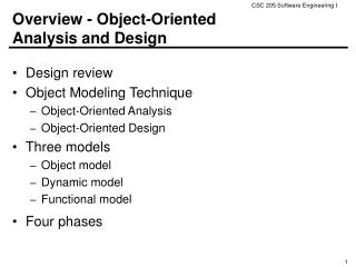
An overview of OOSE development activities and their products problem statement Requirements elicitation nonfunctionalrequirements functionalmodel use case diagram Analysis class diagram analysis object model statechart diagram dynamic model sequence diagram System design
Activities during Object Modeling Main goal: Find the important abstractions • Steps during object modeling 1. Class identification • Based on the fundamental assumption that we can find abstractions 2. Find the attributes 3. Find the methods 4. Find the associations between classes • Order of steps • Goal: get the desired abstractions • Order of steps secondary, only a heuristic • What happens if we find the wrong abstractions? • We iterate and revise the model
Class Identification • Approaches • Application domain approach • Ask application domain experts to identify relevant abstractions • Syntactic approach • Start with use cases • Analyze the text to identify the objects • Extract participating objects from flow of events • Design patterns approach • Use reusable design patterns • Component-based approach • Identify existing solution classes.
Class identification is a Hard Problem • One problem: Definition of the system boundary: • Which abstractions are outside, which abstractions are inside the system boundary? • Actors are outside the system • Classes/Objects are inside the system. • An other problem: Classes/Objects are not just found by taking a picture of a scene or domain • The application domain has to be analyzed • Depending on the purpose of the system different objects might be found • How can we identify the purpose of a system? • Scenarios and use cases => Functional model
There are different types of Objects • Entity Objects • Represent the persistent information tracked by the system (Application domain objects, also called “Business objects”) • Boundary Objects • Represent the interaction between the user and the system • Control Objects • Represent the control tasks performed by the system.
Example: 2BWatch Modeling To distinguish different object types in a model we can use the UML Stereotype mechanism Button Year ChangeDateControl Month LCDDisplay Day Entity Objects Control Object Boundary Objects
<<Entitity>> Month <<Boundary>> LCDDisplay <<Entity>> Day Naming Object Types in UML • UML provides the stereotype mechanism to introduce new types of modeling elements • A stereotype is drawn as a name enclosed by angled double-quotes (<<, >>) and placed before the name of a UML element (class, method, attribute, ….) • Notation: <<String>>Name <<Boundary>> Button <<Entity>> Year <<Control>> ChangeDateControl Entity Object Control Object Boundary Object
UML is an Extensible Language • Stereotypes allow you to extend the vocabulary of the UML so that you can create new model elements, derived from existing ones • Examples: • Stereotypes can also be used to classify method behavior such as <<constructor>>, <<getter>> or <<setter>> • To indicate the interface of a subsystem or system, one can use the stereotype <<interface>> (Lecture System Design) • Stereotypes can be represented with icons and graphics: • This can increase the readability of UML diagrams.
Object Types allow us to deal with Change • Having three types of objects leads to models that are more resilient to change • The interface of a system changes more likely than the control • The way the system is controlled changes more likely than entities in the application domain • Object types originated in Smalltalk: • Model, View, Controller (MVC) Model <-> Entity Object View <-> Boundary Object Controller <-> Control Object
Finding Participating Objects in Use Cases • Pick a use case and look at flow of events • Do a textual analysis (noun-verb analysis) • Nouns are candidates for objects/classes • Verbs are candidates for operations • This is also called Abbott’s Technique • After objects/classes are found, identify their types • Identify real world entities that the system needs to keep track of (FieldOfficer Entity Object) • Identify real world procedures that the system needs to keep track of (EmergencyPlanController Control Object) • Identify interface artifacts (PoliceStation Boundary Object).
Example for using the Technique Flow of Events: • The customer enters the store to buy a toy. • It has to be a toy that his daughter likes and it must cost less than 50 Euro. • He tries a videogame, which uses a data glove and a head-mounted display. He likes it. • An assistant helps him. • The suitability of the game depends on the age of the child. • His daughter is only 3 years old. • The assistant recommends another type of toy, namely the boardgame “Monopoly".
Part of speech UML model component Example Proper noun object “Monopoly” Improper noun class Toy Doing verb operation Buy, recommend being verb inheritance is-a having verb aggregation has an modal verb constraint must be adjective attribute dangerous transitive verb operation enter intransitive verb constraint, class, association depends on Mapping parts of speech to model components (Abbot’s Technique)
The customer enters the store to buy a toy. It has to be a toy that his daughter likes and it must cost less than 50 Euro. He tries a videogame, which uses a data glove and a head-mounted display. He likes it. store enter() ? enter() daughter daughter age suitable * Toy price buy() like() toy buy() toy boardgame videogame Generating a Class Diagram from Flow of Events Flow of events: Customer customer enters store buy toy daughter less than 50 videogame An assistant helps him. The suitability of the game depends on the age of the child. His daughter is only 3 years old. The assistant recommends another type of toy, namely a boardgame. The customer buy the game and leaves the store depends age boardgame type of toy
Ways to find Objects • Syntactical investigation with Abbot‘s technique: • Flow of events in use cases • Problem statement • Use other knowledge sources: • Application knowledge: End users and experts know the abstractions of the application domain • Solution knowledge: Abstractions in the solution domain • General world knowledge: Your generic knowledge and intution
Order of Activities for Object Identification • Formulate a few scenarios with help from an end user or application domain expert • Extract the use cases from the scenarios, with the help of an application domain expert 3. Then proceed in parallel with the following: • Analyse the flow of events in each use case using Abbot's textual analysis technique • Generate the UML class diagram.
Steps in Generating Class Diagrams • Class identification (textual analysis, domain expert) • Identification of attributes and operations (sometimes before the classes are found!) • Identification of associations between classes • Identification of multiplicities • Identification of roles • Identification of inheritance
Who uses Class Diagrams? • Purpose of class diagrams • The description of the static properties of a system • The main users of class diagrams: • The application domain expert • uses class diagrams to model the application domain (including taxonomies) • during requirements elicitation and analysis • The developer • uses class diagrams during the development of a system • during analysis, system design, object design and implementation.
Who does not use Class Diagrams? • The client and the end user are usually not interested in class diagrams • Clients focus more on project management issues • End users are more interested in the functionality of the system.
Developers have different Views on Class Diagrams • According to the development activity, a developer plays different roles: • Analyst • System Designer • Object Designer • Implementor • Each of these roles has a different view about the class diagram (the object model).
The View of the Analyst • The analyst is interested • in application classes: The associations between classes are relationships between abstractions in the application domain • operations and attributes of the application classes • The analyst uses inheritance in the model to reflect the taxonomies in the application domain • Taxonomy: An is-a-hierarchy of abstractions in an application domain • The analyst is not interested • in the exact signature of operations • in solution domain classes
The View of the Designer • The designer focuses on the solution of the problem, that is, the solution domain • The associations between classes are now references (pointers) between classes in the application or solution domain • An important design task is the specification of interfaces: • The designer describes the interface of classes and the interface of subsystems • Subsystems originate from modules (term often used during analysis): • Module: a collection of classes • Subsystem: a collection of classes with an interface • Subsystems are modeled in UML with a package.
Goals of the Designer • The most important design goals for the designer are design usability and design reusability • Design usability: the interfaces are usable from as many classes as possible within in the system • Design reusability: The interfaces are designed in a way, that they can also be reused by other (future) software systems => Class libraries => Frameworks => Design patterns.
The View of the Implementor • Class implementor • Must realize the interface of a class in a programming language • Interested in appropriate data structures (for the attributes) and algorithms (for the operations) • Class extender • Interested in how to extend a class to solve a new problem or to adapt to a change in the application domain • Class user • The class user is interested in the signatures of the class operations and conditions, under which they can be invoked • The class user is not interested in the implementation of the class.
Why do we distinguish different Users of Class Diagrams? • Models often don‘t distinguish between application classes and solution classes • Reason: Modeling languages like UML allow the use of both types of classes in the same model • “address book“, “array" • Preferred: No solution classes in the analysis model • Many systems don‘t distinguish between the specification and the implementation of a class • Reason: Object-oriented programming languages allow the simultaneous use of specification and implementation of a class • Preferred: We distinguish between analysis model and object design model. The analysis design model does not contain any implementation specification.
Analysis Model vs. Object Design model • The analysis model is constructed during the analysis phase • Main stake holders: End user, customer, analyst • The class diagrams contains only application domain classes • The object design model (sometimes also called specification model) is created during the object design phase • Main stake holders: class specifiers, class implementors, class users and class extenders • The class diagrams contain application domain as well as solution domain classes.
Analysis Model vs Object Design Model (2) • The analysis model is the basis for communication between analysts, application domain experts and end users. • The object design model is the basis for communication between designers and implementors.
Summary • System modeling • Functional modeling+object modeling+dynamic modeling • Functional modeling • From scenarios to use cases to objects • Object modeling is the central activity • Class identification is a major activity of object modeling • Easy syntactic rules to find classes and objects • Abbot’s Technique
Summary cntd • Class diagrams are the “center of the universe” for the object-oriented developer • The end user focuses more on the functional model and usability. • Analysts, designers and implementors have different modeling needs • There are three types of implementors with different roles during • Class user, class implementor, class extender.