Download
1 / 14
160 likes | 300 Views
Thermal Compensation Installation at LHO Dave Ottaway, Ken Mason, Stefan Ballmer- MIT Mike Smith, Phil Willems - Caltech Cheryl Vorvick, Gerardo Moreno, Daniel Sigg- LHO LSC Meeting, March 15-18 2004, LLO. ?. Initial LIGO Thermal Compensation Concept. CO 2 Laser. ZnSe viewport.

E N D
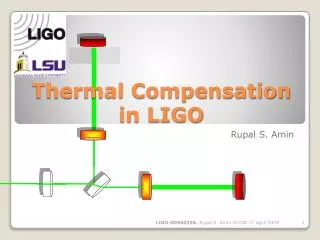
Thermal Compensation Installation at LHO Dave Ottaway, Ken Mason, Stefan Ballmer- MIT Mike Smith, Phil Willems- Caltech Cheryl Vorvick, Gerardo Moreno, Daniel Sigg- LHO LSC Meeting, March 15-18 2004, LLO LIGO Laboratory
? Initial LIGO Thermal Compensation Concept CO2 Laser ZnSe viewport Over-heat pattern: Inner radius = 4cm Outer radius =11cm Over-heat correction aperture Under-heat correction aperture Inhomogeneous correction aperture • Imaging target onto the TM limits the effect of diffraction spreading • Modeling suggests a centering tolerance of 10 mm required to maintain good correction LIGO Laboratory
Thermal Compensation Implementation LIGO Laboratory
Thermal Compensator Layout LIGO Laboratory
Thermal Compensation Projector Annulus Mask Central Heat Mask No Masks • Intensity variations across annulus image due to small laser spot size • Modeling suggests that this should not be an issue • Projection optics work well • AOM distortion above 3W causes intensity centroid shift (these images all taken at 1 Watt CO2 laser power exiting AOM) LIGO Laboratory
Thermal Compensation Controls LIGO Laboratory
PRM Results – Mode Images at AS Port (both ITMs heated) RF sidebands-------------------------------------------------------------------------------------------------->| no heating 30 mW 60 mW 90 mW RF sidebands--------------------------------------------------------------------->| Carrier 120 mW 150 mW 180 mW (thru unlocked IFO) LIGO Laboratory
PRM Results –Sideband Buildup • Max buildup at ~90 mW TC • TC increased in 30 mW steps • IFO is sideband locked PRM with wavefront sensing LIGO Laboratory
PRM Optical Gain during heating • Maximum gain at ~90 mW central heating • Same heating optimizes RF sideband buildup • Same heating makes RF sideband mode resemble carrier mode LIGO Laboratory
Full Interferometer Results • Interferometer locked at 1 Watt • 90 mW central heating applied to both ITMs • Central heating reduced • Maximum power with 45 mW heating • ?? No change in AS_DC throughout LIGO Laboratory
Summary of Results State SPOB GSB -------------------------------------------------------------------------------- State 2 cold 85 7.0 State 2 hot (90 mW CO2) 152 12.5 State 2 max (tRM / (1 - rRM rM rITM))2 14 -------------------------------------------------------------------------------- State 4 cold 160 13 State 4 warm (0.8W input) 190 16 State 4 hot (2.3W input, no TCS) 240 20 State 4 hot (0.8W input, 45mW CO2) 320 26.5 State 4 max (tRM / (1 - rRM rM))2 30 -------------------------------------------------------------------------------- LIGO Laboratory
PRM Asymmetric Heating • Maximum achieved with 120 mW on ITMy only • SPOB build-up is the same gotten with common heating • ITMx requires 200 mW to maximize SPOB to lower value; some asymmetry observed in mode structure LIGO Laboratory
PRM Asymmetric Heating – Optical Gain LIGO Laboratory
Issues to Resolve • Errors/difficulties in installation reduce the viewport aperture- annulus heating not fully functional yet • Different behavior of ITMx and ITMy • Optimum compensation occurs with 90mW central heating, yet models predict less than half this • Tests show 90% of CO2 laser power is absorbed by ITM • Misalignment of CO2 laser beam cannot explain discrepancy LIGO Laboratory