Download
1 / 32
320 likes | 433 Views
SuperSVD Mechanics and Cooling. Seminar at Riken University. Origami Concept. 300 µm double sided silicon detector Thinned readout chips (APV25) on sensor Strips of bottom side are connected by flex fanouts wrapped around the edge Shortest possible connections high signal-to-noise ratio

E N D
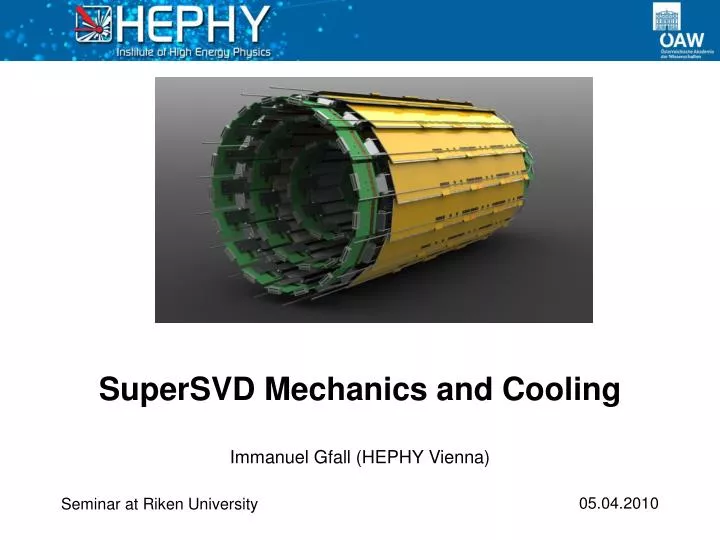
SuperSVD Mechanics and Cooling Immanuel Gfall (HEPHY Vienna) Seminar at Riken University
Origami Concept • 300 µm double sided silicon detector • Thinned readout chips (APV25) on sensor • Strips of bottom side are connected by flex fanouts wrapped around the edge • Shortest possible connections high signal-to-noise ratio • All readout chips are aligned single cooling pipe • Total averaged material budget: 0.58% X0 • DSSD material budget: 0.3% X0 • SVD including sensors, readout electronics, mechanics and cooling is developed in Vienna Rohacell Insulation APV25 Fanouts DSSD 3-Layer Kapton Cooling Tube Immanuel Gfall (HEPHY Vienna)
DSSD • First 6’’ sensors are delivered • Dimensions: 59.6 x 124.88 mm • Readout pitch p-side strips: 75 µm • Readout pitch n-side strips: 240 µm • Number of readout strips p-side: 768 • Number of readout strips n-side: 512 • Wedge sensors in forward region • Wedge readout p-side pitch: 75-50 µm • Wedge readout n-side pitch: 240 µm • Same number of readout strips as the rectangular sensors • Total Number of sensors: 187 Immanuel Gfall (HEPHY Vienna)
Mechanics Immanuel Gfall (HEPHY Vienna)
Design Goals • Lowest possible material budget • Gravitational sag as low as possible • Sag has to be stable over time • Minimum coefficient of thermal expansion • Low moisture susceptibility • Radiation hardness up to 10 Mrad • Has to be compliant with the Origami concept • Cost efficiency Immanuel Gfall (HEPHY Vienna)
Current Barrel Layout Origami Cooling Tubes Slanted Sensors Hybrid Boards Immanuel Gfall (HEPHY Vienna)
Initial Design Options Cooling Pipe Sensor • Carbon fiber sandwich ribs concept • Sensor bottom side is the only available contact surface Sandwich Member Support Ribs Origami placed on top Sensor • Carbon fiber sandwich member concept • Member structure sandwiched by sensor and kapton hybrid Immanuel Gfall (HEPHY Vienna)
Current Design Choice • Carbon fiber sandwich rib design won the race against sandwich member design • Offers sufficient mechanical support • Less complicated fabrication • R&D for rib concept is less time consuming • Fewer electrical issues Immanuel Gfall (HEPHY Vienna)
Carbon Fiber Sandwich Mounting Points Rohacell Core Carbon Fiber Reinforced Plastic Layers (CFRP) • Core has a high shear modulus • Core distances high modulus carbon fibers from neutral fiber • Pull strength comes from CFRP layers, shear resistance comes from Rohacell core • Both combined result in extremely stiff but light strucutre Immanuel Gfall (HEPHY Vienna)
Ladder 6 Design • Sandwich structure is the key feature • Ribs are mechanically coupled through sensors and mount strucutre • Mount structure also supports hybrid board • Precision shims even out mechanical imperfections • Sensor mount structure distances sensors from electrical conducting CFRP Sensor Precision Shims Origami Sensor Sensor Mount Structure Mount Structure Carbon Fiber Hybrid Board CF Reinforcement CF Ribs Immanuel Gfall (HEPHY Vienna)
Maximum Radiation Length Distribution APV Kapton Pipe Coolant Sensor CFRP Rohacell Immanuel Gfall (HEPHY Vienna)
Prototype Developement • First stage: ‘What are we dealing with?’ • Second stage: ‘How can we optimize the building process?’ • Third stage: ‘How do we assemble the ladder?’ • Fourth stage: ‘What do we build in house and what goes to manufacturers?’ • Fifth stage: Final production and quality control of all ribs Inverse configuration Double side layup Single side layup Immanuel Gfall (HEPHY Vienna)
Prototype Issues • Fiber layup and vacuum bagging by hand is extremely time consuming (~4h for two ribs) • Precision of layup quality is insufficient • Bad precision of water cutting (need for a new manufacturer) • Core foam is only available in 3 mm (adds 0.005% X0 compared to 2mm) • New building approach:first CF ply layup, then water cutting Laminated Board Dummy Rib Immanuel Gfall (HEPHY Vienna)
Positive Feedback • Sandwich rib concept (CFSR) works • Gravitational sag is within expected magnitude • Extremely light structure (4g) • High modulus fiber only 65µm thick • Slightly improved material budget (0.01% X0) CFSR merits compared to SVD 2 Zylon ribs: • CFSR ~30% lighter than Zylon • Avg. material budget:1mm Zylon = 0.691% vs. 3mm CFSR = 0.568% X0 • No need for CF bridge as in SVD 2 Immanuel Gfall (HEPHY Vienna)
End Ring Mounts • Support point for ladders • Support hybrid boards • Connect ribs to end rings • Will provide cooling contact between APVs and end rings • Provide some necessary degrees of freedom • Two or more different geometries necessary APV Groove Precision Hole for Ladder Support Pin APV Groove Hybrid board mount points Immanuel Gfall (HEPHY Vienna)
Endrings • Ladders are attached to Endrings • Endrings are mounted on beam masks • Endrings offer space for cable and cooling tube routing • Tungsten beam masks shield sensors from beam background • Slanted sensor in forward region complicates space allocation • Different end ring mount designs help to allocate more space Mean distance of opening: ~5 mm Layers Layer 3 mounting Masks End rings Immanuel Gfall (HEPHY Vienna) Immanuel Gfall (HEPHY Vienna) 16
Ladder 3 • Different design approach than other ladders • Goal: reduced material budget (~0.35% X0) • Self supporting sensors Support Structure Sensor Hybrid Board Glue Contact • Length of unsupported sensors ~200mm • Tests with real sensors will show if it works in principle • Support structure material: PEEK + Carbon fiber • FEM simulation suggests that the support structure is sufficiently stable • Sensor size decision is still pending (~124 mm x 38 mm) Immanuel Gfall (HEPHY Vienna)
Support Structure Options • Option 2: Block • Decouples hybrid CTE from silicon sensor CTE • Mounting on PXD or modified beam masks • Option 1: Clamp • Flat design saves space • Difficult mounting • CTE missmatch Mounting Points Mounting Area Sensor Contact Sensor Contact Clamp Structure Design choice will strongly depend on mask and PXD design Immanuel Gfall (HEPHY Vienna)
Layer 3 • Final ladder number is still pending • 7 ladders ease space problems • 8 ladders might be needed for proper overlap • Simulations for alignment are planned • Sensor width will be chosen by mechanical restraints Immanuel Gfall (HEPHY Vienna)
Immediate Outlook Mechanics • Finishing rib construction and evaluation • Elaborating endring mounts and fixtures • Building and testing of fully assembled ladder 6 prototype • Finally production of ribs for all 3 layers if conducted tests successful Parallel tasks: • Layer 3 design/construction/evaluation • Building of a full SVD Barrel mockup for mechanical and cooling studies • Development of a cooling solution Immanuel Gfall (HEPHY Vienna)
Cooling Immanuel Gfall (HEPHY Vienna)
Cooling Boundary Conditions • Power dissipation/APV: 0.4 W • 1 Origami sensor features 10 APVs • Total Origami power dissipation: 356 W • 404 W dissipated at the hybridboards • Total SVD power dissipation: 760 W Immanuel Gfall (HEPHY Vienna)
Cooling Requirements • Smallest possible material budget in the acceptance region • Operating temperature @ -20°C for SNR improvement • Significant part of the heat is dissipated at preamp/shaper of APV25 • Radiation hard coolant • Cooling system needs to handle 1kW+ of dissipated heat (including PXD) • Cooling fluid should be dielectric, non-flameable and non corrosive Immanuel Gfall (HEPHY Vienna)
Cooling Inside Acceptance Region • Cooling with thin cooling tubes (1.4mm outer Ø) • 2 or more ladders connected with one cooling loop • Inlet and outlet at backward region Origami Module • Small contact surface, should be enlarged to maximize efficiency • Thin tubes = better heat flow APV SilPad Cooling Tube Rohacell Insulation Fanout Immanuel Gfall (HEPHY Vienna)
Cooling Outside Acceptance Region • Cooling of end rings is nessecary Ideas: • Thermal contact between end rings and APVs through thermally conducting material • Serpentine cooler scheme • APVs on top of hybrid board cooled by heatsinks and low temperature environment • Forward regioncoolingbecomes a spaceissue Immanuel Gfall (HEPHY Vienna)
CO2 Cooling Basically CO2 fulfills all above requirements • Allows small diameter cooling tubes (1.4 mm x 0.05 mm) • Very small flow rate (~0.65 m/s for 4 ladders per loop) • Small temperature gradient (~1°C over 3.2 m) • Excellent heat transport • Tube thickness complies with Japanese national laws (tmin= 0.017mm for d=1.4 mm and P=20 bar) Downside: • Considerable development effort • Cost of cooling plant (2kW: >40,000€ or 4.9 MYen) • High pressure requires careful design and engineering • Cool Volume needs proper insulation to protect adjacent subdetectors Immanuel Gfall (HEPHY Vienna)
How does CO2 cooling work Conventional approach • Evaporative two phase system • Liquid CO2 stored in heat exchanger • Supply lines feed liquid CO2 to capillary • Pressure reduction to ~19 bar = -20°C • Evaporation in cooling tubes (two phase state and heat transfer) • 2 phase fluid leaves evaporator at 30% saturation • Remaining enthalpy used to sub-cool liquid CO2 to improve efficiency • Compression to ~80 bar • Gas to liquid conversion through heat exchanger Immanuel Gfall (HEPHY Vienna)
System Options Conventional System • Compression to 80 bar with rotary compressor • Warm supply lines with high pressure (80 bar) • Various industrial solutions exist • Problems with oil in cooling lines clogging up the system Accumulator design (NIKHEF) • Pressure controlled by Accumulator (Vessel that has a cooling loop and also a heater as pressure of CO2 is regulated by temperature) • Flow is generated by a oil less pump • Heat exchangers have to subcool liquid to prevent cavitation in pump Immanuel Gfall (HEPHY Vienna)
Outlook • Thorough calculation and simulation of thermodynamical parameters • Building a test system (blow system) • Development of the cooling line layout and routing scheme • Evaluation of different cooling schemes • Development of cooling plant (until 2012?) • Tuning and tweaking • First positive test results expected by 2011 Immanuel Gfall (HEPHY Vienna)
Backup Slide Immanuel Gfall (HEPHY Vienna)
CO2 Test System Principle • CO2 supply from bottle at room temperature (56 bar) • Pressure reduction to ~19 bar (capillary) • Phase change (cooling tubes) • Inlet sub cooling with remaining enthalpy toimprove the efficiency • Remaining gas is blowninto the atmosphere Immanuel Gfall (HEPHY Vienna)
C C B B A A D E D Immanuel Gfall (HEPHY Vienna)