Download
1 / 27
280 likes | 593 Views
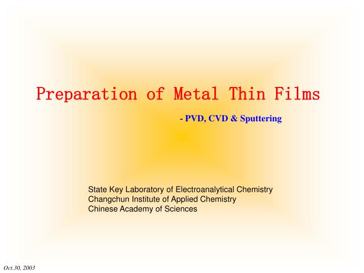
Preparation of Metal Thin Films. - PVD, CVD & Sputtering. State Key Laboratory of Electroanalytical Chemistry Changchun Institute of Applied Chemistry Chinese Academy of Sciences. Steps & General Factors of Thin Film Growth & Nucleation. Target. Medium. Substrate.

E N D
Preparation of Metal Thin Films - PVD, CVD & Sputtering State Key Laboratory of Electroanalytical Chemistry Changchun Institute of Applied Chemistry Chinese Academy of Sciences
Steps & General Factors of Thin Film Growth & Nucleation Target Medium Substrate Production of the appropriate atomic, molecular, or ionic species Transport to the substrate through a medium e.g.: vacuum, electric field, distance, stability of species, concentration of supporting electrolyte, etc. Condensation on substrate The nucleation density and the average nucleus size depend on a number of parameters such as, • the energy of the aim species • the rate of attachment • The activation energy of adsorption & desorption • Thermal diffusion • Temperature • Topography • Chemical nature of the substrate.
Initial Nucleation & Growth Island Layer-by-Layer Stranski-Krastanov (Mixed Type)
Effect of Substrate Temperature on the Lateral Grain Size 100 Å thick Au films deposited at 100, 200, and 300℃ by vacuum evaporation.
Microstructure & Growth Process The small islands start coalescing with each other in an attempt to reduce the surface area. This tendency to form bigger islands is termed agglomeration and is enhanced by increasing the surface mobility of the adsorbed species, as, for example, by increasing the substrate temperature. Except under special conditions, the crystallographic orientation and the topographical details of different islands are randomly distributed,
Formation of large-grain-sized epitaxial/single-crystal films The conditions favoring epitaxial growth are: high surface mobility as obtained at high substrate temperatures, low supersaturation, clean, smooth, and inert substrate surfaces, and crystallographic compatibility between the substrate and the deposit material On the other extreme of thin film microstructures, highly disordered, very fine-grained, noncrystalline deposits with grain size< 20Å and showing halo-type diffraction patterns similar to those of amorphous structures are obtained under conditions of high supersaturation and low surface mobility. The surface mobility of the adsorbed species may be inhibited, for example, by decreasing the substrate teimperature, by introducing reactive impurities into the film during growth, or by codeposition of materials of different atomic sizes and low surface mobilities. Under these conditions, the film is amorphouslike and grows layer by layer.
Effect on Surface Roughness A quantitative measure of roughness, the roughness factor, is the ratio of the real effective area to the geometrical area. Under conditions of low nucleation barrier and high supersaturation, the initial nucleation density is high and the size of the critical nucleus is small. This results in fine-grained, smooth deposits which become continuous at small thicknesses. High surface mobility, in general, increases the surface smoothness of the films by filling in the concavities. Low Tsubstrate ~ large RF (amorphous-like, but mirror-like) High Tsubstrate ~ small RF (epitaxial & single-crystal-like)
Adhesion The adhesion of a film to the substrate is strongly dependent on the chemical nature, cleanliness, and the microscopic topography of the substrate surface. Presence of contaminants on the substrate surface may increase or decrease the adhesion depending on whether the adsorption energy is increased or decreased, respectively. The adhesion of a film can be improved by providing more nucleation centers on the substrate, as by using a fine-grained substrate or a substrate precoated with suitable materials. Loose and porous deposits formed under conditions of high supersaturation and poor vacuum are less adherent than the compact deposits.
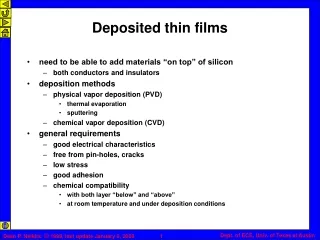
Physical Vapor Deposition Vacuum Evaporatoin Sputtering Glow-Discharge Sputtering Ion-Beam Sputtering Chemical Vapor Deposition Chemical Solution Deposition Autocatalytic Reduction / Electroless Plating Spray Pyrolysis Conversion Coatings Electrochemical Deposition Electrodeposition Anodization Electrophoretic Deposition Cathodic Conversion Classification of Techniques on Thin Film Deposition Vapor Deposition Solution Deposition
Physical Vapor Deposition (PVD) The characteristic feature of PVD techniques is that the transport of vapors from the source to the substrate takes place by physical means. Here, in this way, the vapor species of a solid material is created by thermal evaporation, or by mechanically knocking out the atoms or molecules, and then deposited directly on substrate without any chemical reactions. The mean free path (mfp) of the ambient gas molecules is greater than the dimensions of the deposition chamber and the source-to-substrate distance. Under low-pressure ambient conditions, the transport of the material from the source to the substrate occurs by molecular beams. Low Pressure High Pressure
Physical Vapor Deposition (PVD) Mono-source evaporation/sputtering Multi-source co-evaporation/co-sputtering
Physical Vapor Deposition (PVD) - Vacuum Evaporation As the name implies, the techniques consists of vaporization of the solid material by heating it to sufficiently high temperatures and condensing it onto a cooler substrate to form a film. The simplest and the most common method is to support the material in a filament-basket or boat, which is heated electrically, or is indirectly heated in crucibles of insulating materials such as quartz, graphite, alumina, and zirconia, which are supported in a metal cradle.
Kinetics of Evaporation & Condensation The rate of free evaporation of atoms or molecules from a clean surface of unit area in vacuum is given by Langmuir-Dushman equation, pe - the equilibrium vapor pressure (in Torr) of the evaporant under saturated vapor conditions at a temperature T. M - the molecular weight of the vapor species. The rate of condensation of the vapors depends not only on the evaporation rate but also on the source geometry, its position relative to the substrate, the degree of vacuum, and the condensation coefficient.
Necessary of Vacuum on PVD Because of collisions with the ambient gas molecules, a fraction of the vapors, proportional to exp(-d/) (, mean free path for air), is scattered and hence randomized in direction within a distance d during their transfer through the gas. Thus, pressures lower than 10-5 Torr species and for substrate-to-source distance of ~10 to 50 cm in a vacuum chamber. Good vacuum is also necessary for producing contamination-free deposits (also useful and required for oxidizable species).
Target Medium Substrate Physical Vapor Deposition (PVD) - Sputtering The vapor species are created by mechanically knocking out the atoms or molecules from the surface of a solid material by bombarding it with energetic, non-reactive ions. The ejection process, known as sputtering, occurs as a result of momentum transfer between the impinging ions and the atoms of the target being bombarded.
Characteristics of the Sputtering Process The sputtered species, in general, are predominantly neutral. The sputtering yield, defined as the number of ejected species per incident ion, increases with the energy and mass of the bombarding ions. For higher energies, the yield approaches saturation, which occurs at higher energies for heavier bombarding particles. e.g.: Xe+ ~ 100KeV and Ar+ ~ 20KeV for saturation. Sometimes, at very high energies of the bombarding ions, the yield decreases because of the increasing penetration depth and hence increasing energy lossed below the surface, with the consequence that not all the affected atoms are able to reach the surface to escape. The yield increases as (cos)-1 with increasing obliqueness () of the incident ions. However, at large angles of incidence the surface penetration effect decrease the yield drastically. The yield is rather insensitive to the target temperature except at very high temperatures where it show an apparent rapid increase due to the accompanying thermal evaporation. The energy of the ejected atoms shows a Maxwellian distribution with a long tail toward higher energies. The energies of the atoms or molecules sputtered at a given rate are about one order of magnitude higher than those thermally evaporated at the same rate. However, since sputtering yields are low and the ion currents are limited, sputter-deposition rates ae invariably one to two orders of magnitude lower compared to thermal evaporation rates under normal conditions. The sputtering process is very inefficient from the energy point of view, because most of the energy is converted to heat which becomes a serious limitation at high deposition rates. The sputtering process ensures layer-by-layer ejection from a multicomponent target and results into a homogeneous film on the substrate.
Cathode Diode Sputtering Target - - - - - - - - - - - - - - - - - Cathode Bias Sputtering Target - - - - - - - - - - - - - - - - - + + Ion Platting + + + + Getter Sputtering Magnetron Sputtering Substrate + + + + + + + + + + + + + + + + + + Anode - - - - - - - - - - - - - - - - - Assisted or Triode Sputtering Substrate Insulator + + + + + + + + + + + + + + + + + + Anode RF Sputtering Sputtering – Glow-Discharge Sputtering Glow-Discharge Sputtering by different electrode configurations + + +
Sputtering – Glow-Discharge Sputtering A cheap and simple means of producing ions for sputtering is provided by the well-known phenomenon of glow discharge, which occurs when an electric field is applied between two electrodes in a gas at low pressure (~ 10-2 Torr). The gas breaks down to conduct electricity, above a certain voltage applied between the electrodes, The cathode dark space, across which most of the applied voltage drops, is the most important region for sputtering. Ion and electrons created at breakdown are accelerated across this region. The energetic positive gas ions strike the cathode to produce sputtering and cause emission of secondary electrons which are essential for sustaining the glow discharge. The accelerated electrons produce more ions by collision with gas atoms in the negative-glow region lying adjacent to the cathode dark space.
Sputtering – Glow-Discharge Sputtering The energy of the bombarding ions depends on the accelerating cathode fall (i.e., the voltage across the cathode dark space) and the thickness d of the cathode dark space, which inversely proportional to the gas pressure p, that is pd=const (Paschen’s law) The number of ions striking the cathode current depends on the gas pressure and the applied voltage. Initially, as the gas pressure is increased, the cathode current increases due to increases of the number of the ions, also, at higher gas pressures, the sputtered atoms are prevented from reaching the substrate at the anode because of randomization due to the large number of collisions with the gas molecules. Finally, an effective glow-discharge sputtering can take place only within an optimum pressure range of 20 to 100 mTorr. Since the sputtered species are diffusely scattered by ambient gas molecules during their transit, they reach the substrate in randomized directions and energies. As a result of the diffuse nature of material transport, the atoms deposit at places not necessarily in the line of sight of the cathode. Also, note that because of the collisions the energetic ions hit the cathode at high oblique angles, which is actually helpful in increasing the yield.
e- Ar+ Au Our BAL-TEC SCD 050
Procedures & Attention Pre-sputtering of Cr Wafer (removing the oxide-layer) Pump down properly in the E-3 range Select process-vacuum (with Ar) 2.510-2 mbar Shutter closed Sputter-head cooling on Raise the current from 70 mA to 150 mA continual (during 1 min) Open the shutter for a while Sputtering of Cr Layer Select process vacuum (with Ar) 2.510-2 mbar Shutter closed Sputter-head cooling on Raise the current from 80 mA to 120 mA continual (during 30 sec) Open the shutter for a certain time Sputtering of Au Layer Change the target after Cr layer sputtering Select process vacuum (with Ar) 2.510-2 mbar Shutter closed Sputter-head cooling on Raise the current gradually and stay at 40 mA ~ 60 mA Open the shutter for a setting time Remarks: Pre-sputtering at 100 mA: No chance to remove the oxide-layer!! Often the plasma is not stable in immediately at high current, So please raise the sputter current smoothly (see above)!! If the oxide-layer is thick (if the target is new or not used for a long time), then please remove it without specimens in the chamber!! For the second run directly after that (with inserted samples now), no or only a very short pre-sputtering time is needed!!
Cr underlayer 5-15nm Piranha solution dried Rinsed H2O H2SO4:H2O2=7:3 Substrates Cleaning & Pre-coating Cleaned Substrate 1 Then good adhesion of Au can be obtained at substrate 2 Silanization Improved adhesion of hydrophobic Au at glass (fluxing in propyltrimethoxysilane/toluene solution) a. Haller, I. J. Am. Chem. Soc. 1978, 100, 8050. b. So, H.;Pope, M. T. Inorg. Chem. 1972, 11, 1441.
Cleaning & Regeneration of Sputtered Quartz Solution Composition (only for 4 ~5 pieces): 6ml of Aqua Regia Solution (ratio in mole, HNO3 (65%):HCl(38%) = 1:3) + 0.5ml of H2O2 VHNO3 (65%) = 0.85 ml VHCl (38%) = 5.15 ml VH2O2 (ca.30%) = 0.50 ml Cleaning under Microwave (only suitable for Ag, Au, Pd, Pt, etc., or their alloy, and total metal mass < 0.5g) • 250W 5min • 400W 5min • 650W 5min • 250W 5min • Ventilation 7min • Cooling by water • washing thoroughly by distilled water • dry Attention:Aqua Regia solution must be freshly prepared.
Thick Film Deposition Techniques Liquid-Phase Epitaxy Screen Printing (available in lab of polymer science, microcontact printing, CP) The procedure for screen printing consists of dispersing a paste (or ink) of the material to be deposited on a mesh-type screen on which the desired pattern is photolithographically defined such that open mesh areas in the screen correspond to the configuration to be printed. The substrate is placed a short distance beneath the screen. A flexible wiper, called the squeegee, then moves across the screen surface, deflecting the screen vertically, bringing it into contact with the substrate, and forcing the paste through the open mesh areas. On removal of the squeegee, the screen regains its original position, leaving behind the printed paste pattern on the substrate. The substrate is allowed to stand at ambient temperature for some time to enable the paste to coalesce to form a coherent level film. Melt Spinning Dip Coating, Spinning & Solution Casting
Monitoring & Analyzing Deposition Rate & Thickness Mechanical Method Gravimetric Method Optical Methods (such as interferometric, optically absorbed, ellipsometric, etc.) Radiation Methods (such as back-scattering of , -rays, x-ray fluorescence, etc.) Structure & Morphology Microscope (STM, AFM, SEM, TEM, Optical, etc.) LEED (for structural analysis on the film surface) Composition ESCA (AES, UPS, XPS, etc.) SIMS (Secondary ion mass spectrometer) RBS (Rutherford back-scattering)
Further Readings General • K.L. Chopra, Thin Film Phenomena, McGraw-Hill, New York (1969). • K.L. Chopra, Thin Film Device Applications (1983). Vacuum Evaporation • W. Schlemminger & D. Stark, Thin Solid Films 137 (1986) 49. • C. Marliere, D. Renard & J.P. Chavineau, Thin Solid Films 201 (1990) 317. • D. Hecht & D. Stark, Thin Solid Films 238 (1994) 258. Sputtering • M. Matsui, H. Nagayoshi, G. Muto, S. Tanimoto, K. Kuroiwa & J. Tarui, Jpn. J. Appl. Phys. 29 (1990) 62. • T. Maruyama & T. Morishita, J. Appl. Phys. 77 (1995) 6641. • Y. Inoue, M. Nomiya & O. Takai, Vacuum 51 (1998) 673. • D. Lützenkirchen-Hecht & R. Frahm, J. Synchrotron Rad. 8 (2001), in press. CVD - Electrochemistry • V.I. Birss & C.K. Smith, Electrochim. Acta 32 (1987) 259. • O. R. Melroy, M. F. Toney, G. L. Borges, M. G. Samant, J. B. Kortright, P. N. Ross & L. Blum, J. Electroanal. Chem. 258 (1989) 403. • O.M. Magnussen, J. Hotlos, R.J. Nichols, D.M. Kolb & R.J. Behm, Phys. Rev. Lett. 64 (1990) 2929. • B.M. Jovic, V.D. Jovic & D.M. Drazic, J. Electroanal. Chem. 399 (1995) 197. • S. Taguchi & A. Aramata, J. Electroanal. Chem. 396 (1995) 131. • B.M. Ocko, X.J. Wang & Th. Wandlowski, Phys. Rev. Lett. 79 (1997) 1511. • S. Wu, J. Lipkowski, T. Tyliszczak & A.P. Hitchcock, J. Phys. Chem. B 101 (1997) 10310. • B. Wohlmann, Z. Park, M. Kruft, C. Stuhlmann & K. Wandelt, Colloids and Surfaces A 134 (1998) 15.
The Latest Readings • G. L. Fisher, A. E. Hooper, R. L. Opila, D. L. Allara, N. Winograd, J. Phys. Chem. B 104 (2000) 3267-3273. • Mitsuo Kawasaki, Tomoo Sato, Takumi Tanaka, Kazunori Takao, Langmuir 16 (2000) 1719-1728. • Vincent S. Smentkowski, Progress in Surface Science 64 (2000) 1-58. • S. Bharathi, M. Nogami, S. Ikeda, Langmuir 17 (2001) 7468-7471. • Debora Goncalves, Eugene A. Irene, Langmuir 17 (2001)5031-5038 • Shane C. Street, A. Rar, J. N. Zhou, W. J. Liu, J. A. Barnard, Chem. Mater. 13 (2001)3669-3677.