Download
1 / 38
400 likes | 583 Views
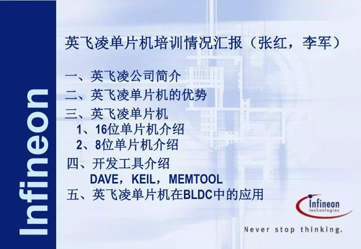
英飞凌单片机培训情况汇报(张红,李军). 一、英飞凌公司简介. 二、英飞凌单片机的优势. May 2006. 三、英飞凌单片机 1 、 16 位单片机介绍 2 、 8 位单片机介绍. Infineon. 四、开发工具介绍 DAVE , KEIL , MEMTOOL 五、英飞凌单片机在 BLDC 中的应用. 一、英飞凌公司简介.

E N D
英飞凌单片机培训情况汇报(张红,李军) 一、英飞凌公司简介 二、英飞凌单片机的优势 May 2006 三、英飞凌单片机 1、16位单片机介绍 2、8位单片机介绍 Infineon 四、开发工具介绍 DAVE,KEIL,MEMTOOL 五、英飞凌单片机在BLDC中的应用
一、英飞凌公司简介 英飞凌科技公司于1999年4月1日在德国慕尼黑正式成立,至今在世界拥有35,600多名员工,2004年公司营业额达71.9亿欧元,是全球领先的半导体公司之一。 西门子半导体事业部作为英飞凌科技(中国)有限公司的前身于1995年正式进入中国市场。现在公司主要为自动化的工业部门提供半导体和系统的解决方案,产品主要应用于汽车电子、有线通讯市场和安全的移动解决方案,以及内存产品。与天津大学、同济大学都联合建立了汽车电子实验室,融科研与教学于一身,是一个高水平的实验室。 英飞凌公司单片机的产品有8位、16位、32位, 16位微控制器的新系列XC166为用户提供了众多性能、存储器和外设可随意选配的产品。用户可轻松找到最适合自己需求的微控制器。
二、英飞凌单片机的优势 • 现在开发产品一般追求两个指标: • 成本和速度。 • 英飞凌单片机的速度最高可到40M。有指令流水线、PEC(相当于DMA,直接内存访问,不通过CPU工作)、CCU6单元(捕捉比较功能),主要应用于电机控制(利用其中的两个定时器T12、T13,可产生不同的PWM波形方便地控制各种电机) • 英飞凌单片机的FLASH存储器具有错误修正功能(英飞凌的宗旨是0缺陷,高效率),具有读保护功能,改善的密码保护机制。 • 有硬件复位功能
二、英飞凌单片机的优势 • 这次培训主要介绍了两款代表机型。 • 最适用于工业应用的16位微处理器XC167CI是目前广泛使用的C166微控制器系列的全新衍生产品,是一款基于增强C166S V2内核架构、性能更加出色的16位微控制器。XC167CI凭借其出色的DSP性能、先进的中断处理能力、功能强大的片上外设集、以及高性能的片上 Flash,能够为要求苛刻的工业和电机控制应用提供最佳的解决方案。除具有C167外设集之外,XC167CI内置灵活的片上PWM产生单元(用于各种电机控制应用)和IIC模块。 • XC886/888CLM广泛适用于车身、工业和农业设备控制、楼宇中的电梯/自动扶梯控制、智能传感器、分布式I/O模块和工业自动化等诸多领域中的组网应用。
英飞凌单片机命名规则 • S A F – X C 8 6 6C L – 2 FRAAA B 0~70℃ (商业级) F -40 ℃~85 ℃ (工业级) K -40~125 ℃ (军用级、汽车级) A 汽车用 I 工业用 Blank 普通用户 Blank 1Kbyte 0 2Kbyte 1 4Kbyte 2 8Kbyte 11 44Kbyte … F Flash R ROM 封装 R TSSOP F TQFP G DSO XC800家族 66 Elektra系列 56 Hermes系列 串口类型 C CAN L LIN M MDU
XC16x存储器组织结构第0段内的RAM,SFR/ESFR和XSFR区域XC16x存储器组织结构第0段内的RAM,SFR/ESFR和XSFR区域
XC16x存储器寻址机制 • 通过CSP+IP来寻址程序空间 • 对于JMPS、CALLS、RESET、Interrupt、TRAP,需要更新CSP,造成额外操作。 • 对于Tiny Memory Model,无需更新CSP。
XC16x存储器寻址机制 • 通过DPP来寻址数据空间(这里的数据包括Constant和RAM中的数据) • 对于Keil编译器,DPP使用的默认约定为: • DPP3用于系统页(sdata、idata),永远等于3 • DPP2默认用于near data、user stack,可以重新规定 • DPP1默认用于near constant,但可以重新规定
指令流水线 • 每一个指令不管是否所有4个阶段都执行也必须都经过这4个阶段。由于经过一个流水线阶段至少需要一个机器周期,所以任何一个指令至少需要4个机器循环完成。然而,流水线允许并行处理可达4个指令,这样大多数指令在复位且流水线装入指令后,似乎是在一个机器循环内完成。
中断/外围事件控制器PEC • 内部RAM从00FCE0H到00FCFEH(位寻址区域)16个字可用于8通道PEC的数据值的目标及源地址。每个通道用一队指针存储在两个连续的字位置,源指针(SRCPx)在低字位置,目的指针(DSTPx,x=7~0)在高字位置。当数据传输时,由PEC通道数选择的源和目的指针可以被访问,并独立于当前的DPP寄存器内容。如果PEC通道未用,这些区域可以用于数据存储。 • PEC数据转换完成可以产生中断。 • 只可以在中断优先级8~15中设置PEC,在0~7内不能。 • 一般多与ADC连用,可以自动求平均。
ADC单元 • 10位逐次逼近比较器,14通道 • 集成的 采样和保持功能 • 模拟信号输入范围从0V~5V • 支持不同的转换模式 • 1、固定通道单次转换 • 2、固定通道连续转换 • 3、自动扫描单次转换:对选中通道组中的每路通道进行转换,各通道产生一个转换结果 • 4、自动扫描连续转换:对选中通道组重复转换 • 5、等待ADDDAT读取模式:前次的转换结果读取之后自动启动转换 • 6、通道插入模式:当硬件触发时启动转换,可将指定通道的转换插入转换组中(自动扫描)
CCU6单元(capture/compare unit)专用于电机控制的模块 • CCU6提供两个独立的用于产生PWM波形的定时器(T12、T13) • CCU6的块交换工作模式尤其适合于无刷直流电机的控制(霍尔传感器或利用反电动势检测的控制) • 附加特点: • 实现无刷直流驱动电机的块切换功能 • 利用霍尔序列进行位置检测 • 用于块切换的自动转速测量 • 综合错误处理 • 通过外部信号( CTRAP )快速紧急终止,无需CPU 干预 • 用于多通道交流驱动的控制模式 • 输出电平可选,与功率级适配
CCU6单元 3个16位捕获/比较定时器
XC866单片机 • XC866 的其他一些主要特性包括:用来产生脉宽调制信号、带有电机控制专用模式的捕获/比较单元(CCU6);功能扩展的10 位模数转换器(ADC),具有如自动扫描和结果累加(用于抗混迭滤波或结果平均)等特性;功能扩展的通用异步收发器(UART),支持本地互连网络(LIN)应用,并为许多器件提供LIN 的底层驱动软件;提供不同的省电模式选择,以满足低功耗应用;用于优化中断处理的智能分页机制,扩展了控制片内外设功能的特殊功能寄存器(SFR )的地址范围。
四、开发工具介绍 • DAVE • KEIL • MEMTOOL
C C A B B A B A B A C C 五、英飞凌单片机在BLDC中的应用 • BLDC-BrushLess DC Motor • Constructed with a permanent magnet rotor and a stator comprising of wire wound poles and stacked steel laminations. • Electrical energy is converted to electrical energy by the magnetic attractive force between permanent magnet and the rotating magnetic field induced in the wound stator poles. STATOR ROTOR
V U W What is BLDC Motor? • Windings commonly connected in star fashion • Trapezoidal and sinusoidal. Sinusoidal motor produces smoother torque but is more difficultly controlled. • Low voltage motors of less that 48 volts are commonly used in automotive, ebikes, robotics etc. • High voltage motors above 100 volts are used in appliances, industrial applications etc. V U W
U V W What is BLDC Motor? + N U W V - S • DC Motor with 3 Brushes • 3-Phase Brush-less DC Motor According to the theory of DC machine, the motor rotational speed can be written as follows: N = ( Ud - I R ) / (Ke ) While, “N” stands for the motor rotational speed “Ud” stands for the DC voltage applied to the motor windings “R” is the pure resistance of the winding while “I” stands for the winding current “Ke” is the magnet coefficient while “” stands for the motor magnetic flux From the above formula, there are two methods to change the speed of DC motor: One is to change the DC voltage of the motor windings (Ud), the other one is to change the magnetic flux of the motor (). As the BLDC motor has permanent magnet rotor, only the first method can be used in practical application. The principal of generating variable DC voltage is to use PWM for chopping: change the duty cycle of the PWM voltage, proportionally change the DC voltage.
Simple Trapezoidal BLDC Motor Model • This is a simplified and representational model of a single pole pair BLDC motor. • Rotor – Made of permanent magnet. • Stator - Three phase windings connected in star fashion. • Hall Sensor – Devices that can detect magnetic field. In this case study, they are placed at 120 electrical degrees apart. H2 A B H0 H1 C
A+ B+ C+ VDC C- A- B- Simple Trapezoidal BLDC Motor Model • For simplicity, the arrow that shows the direction of the energizing current also shows the direction of the magnetic field for each coil. • Magnetic field of stator, it is a vector sum of the magnetic fields of the energized coils. • Magnetic field of rotor (permanent magnet) • Hall sensors output high when ‘N’ is sensed. N H2 A B H0 H1 C S
B+ C+ C+ A+ A+ B+ C- C- B- B- A- A- Torque Characteristic and Commutation Sequence of Trapezoidal BLDC Motor TORQUE H2 A B H0 H1 VDC C
Torque Characteristic and Commutation sequence of BLDC Motor • 六种状态(转子逆时针转动) • H2 H1 H0 A+ A- B+ B- C+ C- • 1 0 1 0 1 0 0 1 0 5 • 1 0 0 0 1 1 0 0 0 1 • 1 1 0 0 0 1 0 0 1 3 • 0 1 0 1 0 0 0 0 1 2 • 0 1 1 1 0 0 1 0 0 6 • 0 0 1 0 0 0 1 1 0 4 • 1 0 1 0 1 0 0 1 0 5
Period Reg. CT1P Mode CTRAP Offset Reg. CT1OF CC0 COUT0 Port Control Logic CC1 Compare Timer 16-bit COUT1 CC Channel 0 CC0 Input Control FCPU CC2 COUT2 CC Channel 1 CC1 deadtimeControl CC Channel 2 CC2 Burst Mode Compare Timer 10/16 bit Input Control Comp Reg. CMP2 FCPU COUT3 CCPOS0 Block Commutation Control Period Reg. CCPOS1 CCPOS2 Block Diagram of CAPCOM6E for Motor Applications Fast emergency stop by hardware 16 bit Timer 12 for capture/ compare functions Compare can be edge or centre aligned Dead time control for prevention of short circuit. Hall input filter in BLDC mode 3 Timer 12 Capture/ compare registers Timer 12 clock divider from 1 to 128 Control of active/ passive levels Timer 13 clock divider from 1 to 128 Timer single shot mode Timer 13 compare output 16 bit Timer 13 for compare function commonly use for modulation Block commutation control for BLDC Hall input pins
CAPCOM6E pins for BLDC drive system A+ B+ C+ MCU 6 6 VDC XC866 DRIVER C- A- B- 3 Phase Inverter ctrap H2 3 3 Hall Sensor inputs H0 H1 Motor
有一个影像寄存器,一旦发现正确的HALL事件,就把MCMPS赋予MCMP,硬件自动更新,6位,每一位对应一个cc6x状态,等于1即导通对应的MOS管(永远只能有两个导通)有一个影像寄存器,一旦发现正确的HALL事件,就把MCMPS赋予MCMP,硬件自动更新,6位,每一位对应一个cc6x状态,等于1即导通对应的MOS管(永远只能有两个导通)
CAPCOM6E Hall Pattern Registers • The CAPCOM6E Peripheral has a register that holds the current and expected hall effect states Current State Exp. State MCMOUTSH value 1 5 0x0D 2 3 0x13 3 1 0x19 4 6 0x26 5 4 0x2C 6 2 0x32 Shadow Register CHE • Correct Hall Event (CHE) effects the transfer. CHE can also generate an interrupt. • There is also a wrong hall event (WHE) that has an associated interrupt. Actual Register CCPOS2 (Hall 2) CCPOS1 (Hall 1) CCPOS0 (Hall 0)
CAPCOM6E Output Pattern Registers • There is also a Register that holds the Next Output Pattern Current State Exp. State MCMOUTSH MCMOUTSL 1 5 0x0D 0x06 2 3 0x13 0x21 3 1 0x19 0x24 4 6 0x26 0x18 5 4 0x2C 0x12 6 2 0x32 0x09 Shadow Register CHE Actual Register CC61 (B+\-) CC60 (A+\-) CC62 (C+\-) COUT62 (Inh C) COUT61 (Inh B) COUT60 (Inh A)
5 5 4 4 1 0 1 1 0 1 1 0 0 1 0 0 4 6 0 0 1 1 0 1 CAPCOM6E Output Pattern Registers • After Commutation, New values for MCMOUTSL and MCMOUTSH must be loaded to prepare for the next commutation 0 1 0 0 1 0 0 1 0 0 1 0 0x12 Shadow Register 0x2C Shadow Register CHE T13 PWM CHE 0 1 1 0 0 0 0x18 0x0D Actual Register Actual Register CCPOS0 P1.5 (Hall H0) CCPOS2 (Hall H2) CCPOS1 (Hall H1) COUT60 (Inh A) COUT61 (Inh B) COUT62 (Inh C) CC60 (A+\-) CC62 (C+\-) CC61 (B+\-)
Commutation sequence of Trapezoidal BLDC Motor with CapCOM6E H[2..0] CC60 H2 COUT60 A B CC61 COUT61 CC62 H0 H1 COUT62 C B A C 0 X 1 2 0 X 1 8 0 X 0 9 0 X 2 1 0 X 2 4 0 X 0 6 MCMOUTL
Generation of Motor Control Code for BLDC Motor with DAvE and Keil • Code generator (DAvE, XC866 dip version 1.5 or higher) • Create a DAvE project • Set up the CapCom6E for the BLDC motor and generate the initialisation code with DAvE. • uVision3 (Keil) • Start the uVision3 compiler and debugger environment. • Add user code to the main and interrupt portion and compile. • Verify design with uVision3 simulator and uVsion3 logic analyzer. • Note: This case study can be done with the evaluation version of Keil uVision 3 which can be downloaded from www.keil.com. DAvE is free and available from www.infineon.com.
Realization with CAPCOM6E for hands on: Basic Brushless DC Motor. Period Reg. CT12P Period Reg. CT12P Mode Mode CTRAP Offset Reg. CT1OF CC0 CC Channel 0 CC0 COUT0 Port Control Logic Port Control Logic CC1 CC Channel 1 CC1 Compare Timer 16-bit Compare Timer 16-bit COUT1 Input Control FCPU CC2 CC Channel 2 CC2 COUT2 Hall Effect Noise Filter deadtimeControl Burst Mode Compare Timer 10/16 bit Input Control Comp Reg. CMP2 FCPU COUT3 CCPOS0 Block Commutation Control Block Commutation Control Period Reg. CT13P CCPOS1 CCPOS2 Hall Effect Sensors
Realization with CAPCOM6E for hands on: Basic Brushless DC Motor. • Typical Switching Pattern for a BLDC • Hall Sequence depends on motor construction • Output pattern levels depends on inverter topology