Download
1 / 7
70 likes | 203 Views
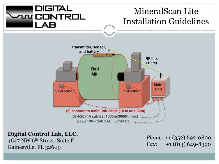
MineralScan Lite Installation Guidelines. transmitter, sensor, and battery. RF link (10 m). Ball Mill. Main Unit. i nlet sensor. outlet sensor. (2) sensors to main unit cable (10 m and 30m). (3) 4-20 mA cables (1000m/3000ft max). p ower 90 – 240 VAC 50/60 Hz.

E N D
MineralScan Lite Installation Guidelines transmitter, sensor, and battery RF link (10 m) Ball Mill Main Unit inlet sensor outlet sensor (2) sensors to main unit cable (10 m and 30m) (3) 4-20 mA cables (1000m/3000ft max) power 90 – 240 VAC 50/60 Hz Digital Control Lab, LLC.4647 NW 6th Street, Suite FGainesville, FL 32609 Phone: +1 (352) 692-0800Fax: +1 (813) 649-8390
MineralScan Lite– System Components The Main Unit should be installed near the mill, so the supplied 10 and 30 meter (30 and 90 ft.) cables coils will reach both the Inlet/Outlet bearing sensors from the Main Base Unit. Main Unit Mill Shell Wireless Sensor Fixed Inlet/Outlet Bearings Vibration Sensors
MineralScan Lite– Fixed Sensors Connection Fixed sensors are shipped with a short 30 cm (~1 ft.) cable and a IP67 waterproof connector at the end. DCL supplies 10 meter and 30 meter (30 ft. and 90 ft.) shielded cable coils that each have a connector atone end of the cable and are open in the other end. These cables are passed (run) through conduit pipes from the sensors to the Main Unit.
MineralScan Lite– Typical Fixed Sensors Installation Fixed Sensors are magnetically attached to both the inlet and outlet bearings covers. Run the supplied cables in conduits to the Main Unit, pull the cables inside of the Main Unit, leave the terminals open, DCL will make the connections during commissioning time.
MineralScan Lite– Main Unit Cables Inlet bearing fixed sensor cable, supplied by DCL, installed by the customer 3x14 AWG power cable supplied & installed by the customer MineralScan Lite Main Unit 120-220 VAC 50/60 Hz power connection Inlet Sensor 3 x 4-20 mA Connections to PLC or DCS Outlet Sensor 3 cables 2x18 AWG shieldedcable supplied & installed by the customer Outlet bearing fixed sensor cable, supplied by DCL, installed by the customer
MineralScan Lite – Main Unit Components Mine Installed Connections Shown in Red 4-20mA Interfaces (pre-wired by DCL) Receiver Board Main Power Circuit Breaker 4-20 mA Connections AC Power Connection
MineralScan Lite– Main Unit Wiring Definitions Mine Installed Connections in Red DCL installed at commission time: 2: Sensor 1 Earth Ground 3: Sensor 1 Vibration signal 4: Sensor 1 DC+ 5: Sensor 1 DC- 6: Sensor 2 Earth Ground 7: Sensor 2 Vibration signal 8: Sensor 2 DC+ 9: Sensor 2 DC- Mine installed before commissioning time: 10: 4-20mA+ (Sensor 1 Level) 11: 4-20mA - (Sensor 1 Level) 12: 4-20mA+ (Sensor 2 Level) 13: 4-20mA - (Sensor 2 Level) 14: 4-20mA+ (Wireless Sensor Level) 15: 4-20mA - (Wireless Sensor Level) 4-20mA Connections Sensor Connections AC Power Circuit Breaker 1. Terminals 2-9 (blue) are the vibration sensor connections and are installed at commission time by Digital Control Lab personnel. AC Power& 4-20mA Outputs (terminals 10-15 in red) should be run and installed ahead of the commissioning date by mine personnel. Note: All 4-20mA signals requires +24VDC external loop power at PLC.