Download
1 / 20
200 likes | 343 Views
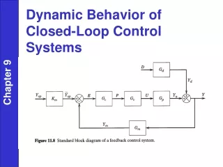
FPGA Implementation of Closed-Loop Control System for Small-Scale Robot. Small-scale robot for urban search and rescue. Bore Hole. Search Occluded Spaces with Tethered Robot Dropped Through Bore Hole. Deployed Configuration. Stowed Configuration. Introduction. Small-Scale Robot

E N D
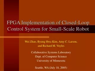
FPGA Implementation of Closed-Loop Control System for Small-Scale Robot
Small-scale robot for urban search and rescue Bore Hole Search Occluded Spaces with Tethered Robot Dropped Through Bore Hole Deployed Configuration Stowed Configuration
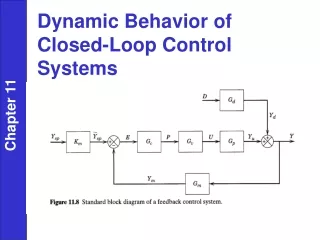
Introduction • Small-Scale Robot • Beneficial for urban search and rescue, military surveillance and countermeasure, planetary exploration • Resource-constrained issues • Mechanical design and controller design CRAWLER functional architecture
Introduction (cont’d) • Tasks of this project • Investigate FPGA implementation of different designs for PID control system to provide performance and resource requirements to Run Time Reconfiguration (RTR) and HW/SW codesign algorithms • Different designs • One-channel parallel and serial designs • Multiple-channel designs • These designs are evaluated in terms of • Area • Power • Speed
Related work • Weiss et al. analyzed different RTR methods on the XC6000 architecture [2]. • Shirazi described a framework and tools for RTR [5]. • Noguera and Badia proposed a HW/SW codesign algorithm for dynamically reconfiguration [3]. • Chen et al. implemented a complete wheelchair controller on an FPGA with parallel PID design [13]. • Samet et al. designed three PID architectures for FPGA implementation – parallel, serial and mixed [14]. • Chan et al. implemented power-efficient design of PID controller using FPGA [Chan04]. • [Chan04]: Y.F. Chan, M. Moallem, and W. Wang, “Efficient implementation of PID control algorithm using FPGA technology,” in 43rd IEEE Conference on Decision and Control, Vol. 5, Dec. 2004, pp. 4885 – 4890.
PID control algorithm • Differential equation Kp : proportional gain, Ti : integral time constant, Td : derivative time constant • Difference equation : Positionalgorithm : Incrementalalgorithm where
One-channel parallel design • Incremental algorithm 4 additions and 3 multiplications
One-channel serial design Department of Electrical Engineering, University of Minnesota
Multiple-channel designs • Channel-level parallel (CLP) designs • Each channel has its own PID unit • Large area, proportional to number of channels • Channel-level serial (CLS) designs • All channels share one PID unit • Small area independent of each channel • More complex control unit • Context switching
Multiple-channel designs • Channel-level parallel (CLP) designs • Each channel has its own PID unit • Large area, proportional to number of channels • Channel-level serial (CLS) designs • All channels share one PID unit • Small area independent of each channel • More complex control unit • Context switching Arithmetic-level parallel (ALP) design Arithmetic-level serial (ALS) design
Experiment system platform • FPGA board (Xport) • Spartan II XC2S150 FPGA • Microprocessor module (GBA) • ARM7TDMI processor, 32-bit RISC
Function test • Step response control • All designs perform correct function. • Fast response, small overshoot and high accuracy. Department of Electrical Engineering, University of Minnesota
Performance test: area • Area test • Test tool • Xilinx ISE, Place & Route Report • Test metric • CLB slices • Logic gates Device resources utilization of designs
Performance test: area (cont’d) • Area • CLS design smallerthan CLP design for large number of channels • But, CLP design smaller for small number of channels • Arithmetic-level serial design always smaller than arithmetic-level parallel, whatever CLP or CLS
Performance test: speed • Speed test • Test tool • Xilinx Timing Analyzer
Performance test: power • Power test • Test tool • Xilinx XPower • Input signals • Set input signal frequency and activity rate: far from accurate • Simulation data file (VCD file): accurate • Simulation tool: ModelSim • Simulation input: real step response experiment data • Two situations • Stable state • Control error = 0 • Dynamic state • Control error 0
Performance test: power (cont’d) • Power dissipation • For the same sampling frequency, CLP+ALS design consumes least power. • But area of CLP is too large for large number of channels. CLS+ALS design has smallest area.
Conclusions • Preliminary work exploring resources-constrained robot control system design using FPGA. • One-channel serial and parallel architectures, and CLS multiple-channel designs for PID closed-loop control. • Functional correctness verified. • For one channel design increasing sampling frequency, • ALS shows less power than ALP. • For small number of channels • CLP+ALS design has smallest area and least power. • For large number of channels • CLP+ALS design still least power, but design is too large. • CLS+ALS design has smallest area. • Performance test methodologies and metrics discussed.
Future work • Implement and test on Virtex-II Pro FPGA. • Run time reconfiguration: reconfigure structure to adapt different situation and terrain. • Use Virtex-II FPGA clock gating structure to improve power efficiency. • Decrease motor power consumption. • Current work: develop FPGA Interface to C3088 camera using Xilinx ML310 board (Virtex-II pro).