Download
1 / 37
471 likes | 842 Views
Sheet Metalworking Chapter 20- Part 1. Manufacturing Processes, 1311 Dr Simin Nasseri Southern Polytechnic State University. SHEET METALWORKING. Cutting Operations Bending Operations Drawing. Sheet Metalworking Defined.

E N D
Sheet MetalworkingChapter 20- Part 1 Manufacturing Processes, 1311 Dr Simin Nasseri Southern Polytechnic State University
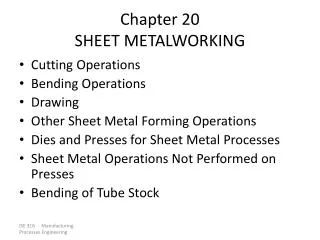
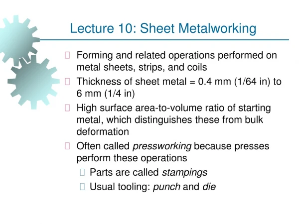
SHEET METALWORKING • Cutting Operations • Bending Operations • Drawing
Sheet Metalworking Defined • Cutting and forming operations performed on relatively thin sheets of metal • Thickness of sheet metal = 0.4 mm (1/64 in) to 6 mm (1/4 in) • Thickness of plate stock > 6 mm • Operations usually performed as cold working Thickness= 0.4 to 6 mm (1/64 to 1/4 in)
Sheet and Plate Metal Products • Sheet and plate metal parts for consumer and industrial products such as • Automobiles and trucks • Airplanes • Railway cars and locomotives • Farm and construction equipment • Small and large appliances • Office furniture • Computers and office equipment
Advantages of Sheet Metal Parts • High strength • Good dimensional accuracy • Good surface finish • Relatively low cost • Economical mass production for large quantities
Sheet Metalworking Terminology • Punch‑and‑die - tooling to perform cutting, bending, and drawing • Stamping press - machine tool that performs most sheet metal operations • Stampings - sheet metal products
Basic Types of Sheet Metal Processes Cutting • Shearing to separate large sheets • Blanking to cut part perimeters out of sheet metal • Punching to make holes in sheet metal Bending • Straining sheet around a straight axis Drawing • Forming of sheet into convex or concave shapes
Sheet Metal Cutting • Figure 20.1 Shearing of sheet metal between two cutting edges: (1) just before the punch contacts work; (2) punch begins to push into work, causing plastic deformation;
Sheet Metal Cutting • Figure 20.1 Shearing of sheet metal between two cutting edges: (3) punch compresses and penetrates into work causing a smooth cut surface; (4) fracture is initiated at the opposing cutting edges which separates the sheet.
Shearing, Blanking, and Punching • Three principal operations in pressworking that cut sheet metal: • Shearing • Blanking • Punching
Shearing • Sheet metal cutting operation along a straight line between two cutting edges • Typically used to cut large sheets • Figure 20.3 Shearing operation: (a) side view of the shearing operation; (b) front view of power shears equipped with inclined upper cutting blade (cutting starts from one edge).
Blanking and • Blanking - sheet metal cutting to separate piece (called a blank) from surrounding stock • Figure 20.4 (a) Blanking.
Example • Cutlery manufacturing: The First step in cutlery manufacture involves blanking the stainless steel or sterling silver to the proper shape. A series of rolling operations then gives the piece the correct thickness. After heat treatment and trimming, the piece has a pattern embossed on it in a stamping operation. Finally, the piece is buffed and polished.
Punching • Punching - similar to blanking except cut piece is scrap, called a slug Figure 20.4 (a) Blanking.
Clearance in Sheet Metal Cutting Distance between punch cutting edge and die cutting edge Depends on hardness and thickness of materials Thickness of metal c • Figure 20.6 Die size determines blank size Db; punch size determines hole size Dh.; c = clearance
Clearance in Sheet Metal Cutting • Typical values range between 4% and 8% of stock thickness • If too small, fracture lines pass each other, causing double burnishing and larger force • If too large, metal is pinched between cutting edges and excessive burr results
Cutting Forces • Important for determining press size (tonnage) • F = S t L • where • S = shear strength of metal; • t = stock thickness, and • L = length of cut edge • (F = Stress x Area = σ. A) Thickness t Length of cut edge or L = perimeter of this rectangular shape
Sheet Metal Bending • Straining sheetmetal around a straight axis to take a permanent bend Figure 20.11 (a) Bending of sheet metal
Sheet Metal Bending • Metal on inside of neutral plane is compressed, while metal on outside of neutral plane is stretched Figure 20.11 (b) both compression and tensile elongation of the metal occur in bending.
Types of Sheet Metal Bending • V‑bending - performed with a V‑shaped die • Edge bending - performed with a wiping die A simple bending machine (press brake)
V-Bending • For low production • Performed on a press brake • V-dies are simple and inexpensive Figure 20.12 (a) V‑bending;
Edge Bending • For high production • Pressure pad required • Dies are more complicated and costly Figure 20.12 (b) edge bending.
Stretching during Bending • If bend radius is small relative to stock thickness, metal tends to stretch during bending. • Important to estimate amount of stretching, so final part length = specified dimension • Problem: to determine the length of neutral axis of the part before bending Bend radius is small. Metal has been stretched.
Bend Allowance Formula • where Ab = bend allowance; • = bend angle; • R= bend radius; • t = stock thickness; and • Kba is factor to estimate stretching (ba stands for bend allowance) • If R < 2t, Kba = 0.33 • If R 2t, Kba = 0.50 • Notice that the formula is written based on the fact that S = rө, and ө = 2πα / 360 in radian.
Original shape Springback Desired deformed shape Springback • Increase in included angle of bent part relative to included angle of forming tool after tool is removed • Reason for springback: • When bending pressure is removed, elastic energy remains in bent part, causing it to recover partially toward its original shape
Springback • Figure 20.13 Springback in bending is seen as a decrease in bend angle and an increase in bend radius: (1) during bending, the work is forced to take radius Rb and included angle b' of the bending tool, (2) after punch is removed, the work springs back to radius R and angle ‘.
Drawing • Sheet metal forming to make cup‑shaped, box‑shaped, or other complex‑curved, hollow‑shaped parts • Sheet metal blank is positioned over die cavity and then punch pushes metal into opening • Products: beverage cans, ammunition shells, automobile body panels • Also known as deep drawing (to distinguish it from wire and bar drawing)
Drawing • Figure 20.19 (a) Drawing of cup‑shaped part: (1) before punch contacts work, (2) near end of stroke; (b) workpart: (1) starting blank, (2) drawn part.
Clearance in Drawing • Sides of punch and die separated by a clearance c given by: • c = 1.1 t • where t = stock thickness In other words, clearance c is about 10% greater than stock thickness
Tests of Drawing Feasibility • Drawing ratio • Reduction • Thickness-to-diameter ratio Successful deep draw progression
Drawing Ratio DR • where Db = blank diameter; • and Dp = punch diameter • Indicates severity of a given drawing operation • Upper limit: DR 2.0 Most easily defined for cylindrical shape: Db Dp Top view Usually Db =< 2Dp
Reduction r • Defined for cylindrical shape: • Value of r should be less than 0.50
Thickness‑to‑Diameter Ratio t/Db • Thickness of starting blank divided by blank diameter • Desirable for t/Db ratio to be greater than 1% • As t/Db decreases, tendency for wrinkling increases
Shapes other than Cylindrical Cups • Square or rectangular boxes (as in sinks), • Stepped cups • Cones • Cups with spherical rather than flat bases • Irregular curved forms (as in automobile body panels) • Each of these shapes presents its own unique technical problems in drawing