Download
1 / 24
300 likes | 1.69k Views
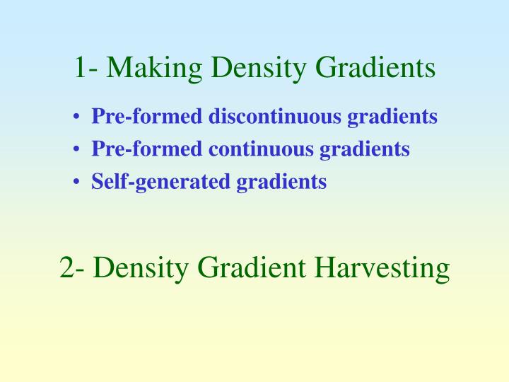
1- Making Density Gradients. Pre-formed discontinuous gradients Pre-formed continuous gradients Self-generated gradients. 2- Density Gradient Harvesting. C. A. B. Discontinuous gradient by overlayering. A. B. C. D. Discontinuous gradient by underlayering. density. top. bottom.

E N D
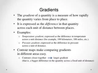
1- Making Density Gradients • Pre-formed discontinuous gradients • Pre-formed continuous gradients • Self-generated gradients 2- Density Gradient Harvesting
C A B Discontinuous gradient by overlayering
A B C D Discontinuous gradient by underlayering
density top bottom Diffusion of a discontinuous gradient
Discontinuous Continuous 45-60 min Rapid formation of continuous from discontinuous gradient
A B T SB SB P M Two-chamber device for continuous gradients
B The Gradient Master
Density (g/ml) 2 min 1.13 2.5 min 3.0 min 1.11 1.09 1.07 1 3 5 7 9 Fraction Number Gradient Master profiles from 10% and 40% iodixanol at 80° and 20 rpm: effect of time
axis of rotation g At rest Spinning g Swinging-bucket rotor
Fixed-angle Vertical g 1g Fixed-angle and vertical rotors
Swinging-bucket Axis of rotation Vertical Sedimentation path length of rotors
A B Axis of rotation Sample/gradient in vertical rotor
time g Self-generated gradients • At 360,000gav iodixanol molecules will start to sediment
350,000g 350,000g 1g 1g Self-generated gradient strategy
Iodixanol self-generated gradient requirements • Rotors with a short sedimentation path length ~ 17 mm • RCF of 180,000-350,000gav
Density (g/ml) 15% iodixanol 1.30 1 h 3 h 1.25 20% iodixanol 1.20 1 h 3 h 1.15 1.10 1.05 1.00 1 3 5 7 9 11 13 15 Fraction Number Effect of time on iodixanol self-generated gradient in the Beckman TLN100 at 365,000g
1.3 15% (170,000g) 30% (170,000g) 15% (353,000g) 1.2 30% (353,000g) Density (g/ml) 1.1 1.0 1 3 5 7 9 11 Fraction Number Effect of RCF and [iodixanol] in Beckman VTi65.1 (3 h)
Gilson Fraction Collector P 96-well plate Harvest gradient into equal volume fractions by tube puncture
Perfluorodecalin Perfluorodecalin P P Upward displacement
P P P P M B EP C 1 2 3 4 Labconco Auto Densi-flow collects from meniscus
MB Labconco Auto Densi-flow linked to a Gilson FC205 Fraction Collector