Download
1 / 31
320 likes | 510 Views
Point Cloud Rendering. Christopher Jeffers, Eric Jensen, Joel Rausch. May13-11. Purpose. Siemens PLM creates software to view and compare 3D models. Some tools, such as 3D laser scanners, output these models as a large group of points in (x,y,z) space.

E N D
Point Cloud Rendering Christopher Jeffers, Eric Jensen, Joel Rausch May13-11
Purpose Siemens PLM creates software to view and compare 3D models. Some tools, such as 3D laser scanners, output these models as a large group of points in (x,y,z) space. This collection of points is known as a "point cloud". Siemens PLM desires a product that can render very large point clouds (100s of millions to a billion points). May13-11
Problem • Computer hardware is very good at drawing sets of triangles (meshes), not optimized for single points. • Difficult and very demanding on hardware to draw every point, especially for very large (a billion point) point clouds. • Possible Solution: Use approximations of points to reduce number of points to be drawn. May13-11
Point Cloud vs. Mesh Mesh Point Cloud May13-11
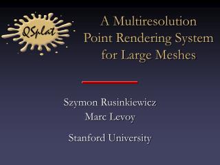
Solution Our research led us to a system created at Stanford University in the year 2000, called QSplat. QSplat uses a very efficient and compressed tree structure to organize point cloud data. Traversing this tree allows us to find where a point should be rendered. Adapting QSplat to current technology allows us to reach our goal of rendering a billion points. May13-11
Program Structure We perform two major tasks on separate, dedicated threads of execution. Traversal puts the points to render in a buffer, and the Renderer reads from this buffer and draws the points to the screen. May13-11
Traversal • Choosing which points to render • Discarding points that are not visible • Points not visible to the camera (frustum) • Points which are behind other points (occluded) • Points which are too small (sub-pixel size) • Performance is affected by how points are organized. May13-11
QSplat Tree Structure Points are leaves in the tree. Clusters of points are bounded by spheres, which form branches. May13-11
Traversing the QSplat Tree Drawing branches approximates a cluster of points. Prune entire tree branches. Prioritize closer branches. May13-11
Rendering Take the points currently in the buffer and render them to screen at an interactive frame rate. May13-11
What is a Splat? Points Splats May13-11
Why Use Splats? Convert a point back to a surface. Real Object Sampled Points Approximated Surface May13-11
Types of Splats Circle (Quad) OpenGL Points Blending Blending 3D Depth Correct Billboard May13-11
Program Structure May13-11
QSplat Tree Structure May13-11
Frame Rate Comparison May13-11
Responsibilities May13-11
Challenges • Working with 13 year-old code • Problems • Uses more complex methods to do simple things because of hardware limitations that no longer exist. • Uses some functionality that have been replaced. • Incompatible number format. • Solutions • Wrapped their interface to fix inconsistency in data. May13-11
Challenges • Working with a billion points • Problem • Large model files • Solution • Compress the file to a tree-based hierarchy, then use memory mapping and a top-down traversal to minimize thrashing. May13-11
Challenges • Designing rendering system to work on varying hardware. • Problem • Not all hardware supports OpenGL functionality. • Supported Platform: • NVidia Quadro • NVidia Geforce • AMD Radeon • Intel Integrated GPUs • Solutions • Check compatibility of hardware. • Limit features used from newer OpenGL versions. May13-11