Download
1 / 20
200 likes | 309 Views
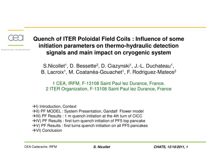
Quench of ITER Poloidal Field Coils : Influence of some initiation parameters on thermo-hydraulic detection signals and main impact on cryogenic system S.Nicollet 1 , D. Bessette 2 , D. Ciazynski 1 , J.-L. Duchateau 1 , B. Lacroix 1 , M. Coatanéa-Gouachet 1 , F. Rodriguez-Mateos 2

E N D
Quench of ITER Poloidal Field Coils : Influence of some initiation parameters on thermo-hydraulic detection signals and main impact on cryogenic system S.Nicollet1, D. Bessette2, D. Ciazynski1, J.-L. Duchateau1, B. Lacroix1, M. Coatanéa-Gouachet1, F. Rodriguez-Mateos2 1 CEA, IRFM, F-13108 Saint Paul lez Durance, France. 2 ITER Organization, F-13108 Saint Paul lez Durance, France • I) Introduction, Context • II) PF MODEL : System Presentation, Gandalf Flower model • III) PF Results : 1 m quench initiation at the 4th turn of CICC • IV) PF Results : first turn quench initiation of PF5 top pancake • V) PF Results : first turns quench initiation on all PF5 pancakes • VI) Conclusion S. Nicollet
I) INTRODUCTION, CONTEXT ITER : 6 Poloidal Field Coils wound in double pancakes using two-in-hand large NbTi CICC with central channel. All pancakes are cooled in parallel. The primary quench detection system is based on resistive voltage. In addition, a secondary quench detection is required & could rely on thermo-hydraulic nature signals. Objective : see the feasibility and necessity of secondary quench detection S. Nicollet
II) PF MODEL : STUDIED CASES • Model based on Gandalf [1] and Flower [2] codes • Previous studies performed on CS [3, 4] and TF [5, 6] of ITER • Study focuses on PF5 coil with different quench initiation without fast discharge : 1) 1 m at the middle of the top pancake 2) first turn of PF5 top pancake 3)all the first turns of PF5 coil Gandalf Parameters [1] L. Bottura et al., A numerical model for the simulation of quench in the ITER magnets, Journal of Computational Physics 125, 26-41, Article N° 0077, 1996. [2] L. Bottura, C. Rosso, Flower , a model for the Analysis of Hydraulic Networks and Processes, CHATS Workshop 15-18 September, 2002. [3] S. Nicollet et al., Cross checking of Gandalf and Vincenta on the CS behaviour during ITER reference scenario, CEC, 2009, in Proceedings Advances in Cryogenic Engineering (2010), pp.1402-1409. [4] S. Nicollet et al., Quench of Central Solenoid : Thermo-Hydraulic detection and main impact on cryogenic system, presented at ICEC 23rd Conference, July 2010. [5] S. Nicollet, B. Lacroix D. Bessette, R. Copetti, J.L. Duchateau, M. Coatanea-Gouachet, F. Rodriguez-Mateos, Thermal-Hydraulic Behaviour of the ITER TF System during a Quench Development, Symposium On Fusion Technology, Porto, 2010 [6] S. Nicollet, D. Bessette, D. Ciazynski, M. Coatanéa-Gouachet, J.L. Duchateau, B. Lacroix, F. Rodriguez-Mateos, Thermal Behaviour and Quench of the ITER TF System during a Fast Discharge and Possibility of a Secondary Quench Detection, Magnet Technology Conference, MT22, 2011, Marseille. S. Nicollet
II) PF MODEL : GANDALF MODEL Gandalf Parameters GANDALF Code [1] is the numerical implementation of a 1-D model for the thermohydraulic simulation of Cable In Conduit Conductor. Model of 4 independent components: the strands, the conduit, the bundle helium and central helium. The boundary conditions (inlet pressure, inlet temperature and massflow) are assumed to be given. I, B (x,t) In the case of a quench, the Joule heat generation is computed consistently with the non-linear critical current density correlation. The solver decides whether a quench or a recovery has taken place. [1] L. Bottura et al., A numerical model for the simulation of quench in the ITER magnets, Journal of Computational Physics 125, 26-41, Article N° 0077, 1996. S. Nicollet
II) PF MODEL : PF Cryogenic loop with FLOWER • For the model of all PF Coils in Flower scheme: • one pancake of one PF coil modelled with Gandalf • other pancakes and other PF coils modelled with Flower using compressible heated channels (as well as the inlet and outlet channel in the feeders) • m pump = 1.6356 kg/s. • regulation valve for each PF Coil (smooth tube same DP=0.62 MPa). • Cryolines • 10 relief valves extremities (2.0 MPa). • envisaged sensor locations for secondary detection in V8/V3 (inlet/outlet of the inlet/outlet feeder, inside CTB). [10]S. Nicollet, J.L. Duchateau, B. Lacroix, M. Coatanéa-Gouachet , ITER CONTRACT ITER/CT/09/4300000014, Deliverable 2.4 : Study of PF system quench behaviour on selected cases, 26th July 2011. S. Nicollet
II) PF MODEL : CONDUCTOR Helium inlets @innermost turns, helium outlet (electrical joints) @ outer radius • PF current follows operating scenario & not discharged study “undetected quench” • PF5 top pancake magnetic field : 4.616 T (at inlet) < B < 3.371 T (at outlet, with 7 paliers) • Jc parameterisation NbTi strand experimental data, following method recommended by IO [7]. • Electrical field E(I,B,T) computed locally from power law considering B peak value • PF2-5 and CC conductors cabled from CN NbTi strand cu:noncu ratio 2.3, parameters: Bc20 = 13.72 T, Tc0 = 8.79 K, m = 1.89, C0 = 113200 106 AT/m², α= 1.00, β = 0.98, γ = 1.96, n= 1.70 [7] D. Bessette, Data Package for simulating the in-coil operation of the PF and CC conductors during the reference scenario #2 15MA baseline, 7 may 2011. S. Nicollet
II) PF MODEL : SYSTEM PRESENTATION Each channel defined hydraulic characteristics (flow area AHe, wetted perimeter Pw). friction factors derived from experimental measurements [8] for bundle region fb and central spiral fh. The parallel channels where supercritical helium flows with possibility of heat transfer and mass exchange. equivalent heat transfer correlation determine from friction factor [9] : Reynolds Colburn analogy central cooling channel aims reduce DP; DPL = 140 Pa/m for PF5 with m=8.7 g/s, P=0.55 MPa, T=5 K regulation valve for each PF Coil dedicated smooth tube (ST) same DP=0.62 MPa. important remark :total mass flow rate for the global system of PF and CC Coils is 1.8 kg/s following model is limited to PF coils system m= 1.6356 kg/s. [8] Nicollet, S., et al., “Dual channel cable in conduit thermohydraulics: Influence of some design parameters”, IEEE Trans. Applied Superconductivity, 10, N°1, 2000, pp. 1102-1105. [9] Nicollet, S., Ciazynski, D., Duchateau, J .L., Lacroix, B. Renard, B., Evaluation of the ITER Cable In Conduit Conductor heat transfer, proceedings of 20th ICEC Conference, Beijing, China, 2004, pp.589-592 [10] S. Nicollet, J.L. Duchateau, B. Lacroix, M. Coatanéa-Gouachet , ITER CONTRACT ITER/CT/09/4300000014, Deliverable 2.4 : Study of PF system quench behaviour on selected cases, 26th July 2011. S. Nicollet
II) PF MODEL : Choice of PF5 top pancake • quench initiation with Minimum Quench Energy (MQE). • PF5 Coil with higher B, quench (x,t) temperature margin is minimum: • highest current Imax = -45 kA at t= 608.5 s of 4th pulse (P, T given from previous studies) • PF5 pancake withmaximum heat load : top pancake • - steady state heat load due to eddy currents in support of PF5 with 52W / 368m = 0.1413W/m • heat loads due to nuclear heating with 131W/ (2*368) = 0.178 W/m), for time = 130s to 530s during plasma; the total heat load during this period is 0.32 W/m. • In following figures t=0 s corresponds to t= 600 s of the 4th scenario • quench initialised t=8.5 s with a heat duration of 1s(until time =9.5 s), corresponding to the beginning of the quench. • In case of fast discharge, for PF5 conductor, a detection voltage of 0.1 V associated with a holding time of 1 s is taken to trigger the fast discharge. [10] S. Nicollet, J.L. Duchateau, B. Lacroix, M. Coatanéa-Gouachet , ITER CONTRACT ITER/CT/09/4300000014, Deliverable 2.4 : Study of PF system quench behaviour on selected cases, 26th July 2011. S. Nicollet
III) PF Results : 1 m quench initiation at the 4th turn of CICC • This quench corresponds to MQE= 1.4 kJ (1400 W/m, 185 m < x < 186 m, 1 s, t=8.5 s to 9.5 s). • Tco =5.10 K, Tcs =7.04 K, DTmargin = 1.96 K • Conductor Joule heating very important =150 MJ (t=50 s) • quench propagation velocity progressively increase (~70 m/s for both normal fronts) • Whole conductor 367 m quenched in 16 s S. Nicollet
III) PF Results : 1 m quench initiation at the 4th turn of CICC I high P increase rapidly & acceleration / reverse of mass flow Pmax= 11 MPa (middle of CICC) mass flow are 0.4 kg/s outlet -0.4kg/s inlet CICC. T increase rapidly, Tmax= 100 K (t=20s) t>=25 s , maximal velocity = 7 m/s, vb= 4 m/s & vh= 17 m/s. velocities keep increasing whereas the mass flow rate is decreasing, as the helium temperature is increasing S. Nicollet
III) PF Results : 1 m quench initiation at the 4th turn of CICC P, T, m @ Volume 31 inlet of Junction J15 & Volume V16, outlet of the junction J9, @ Cold Termination Box (CTB), extremities of the feeder, where sensors located P & T signals not sufficient for a secondary detection most difficult case, except signal of mass flow rates difference (0.1 kg/s 10 s after quench) S. Nicollet
IV) PF Results: First turn quench initiation on top pancake “important quench” performed: with all the pancakes (Junction J7) quenching at the same time, at the first turns, in order to assess the necessity of secondary quench detection. For this purpose, the study of one quench of the top pancake (J1) is performed; Joule heating applied (dx=10 m &dt=0.1 s) along corresponding Flower Module (J7). • MQE = 17.5 kJ (350 W/m along 50 m from t=8.5 s to 9.5 s). • T initially at 4.83 K > Tcs = 6.71 K DTmargin = 1.88 K • quench propagation rapid = 35 m/s whole conductor 367 m quenched in 11 s S. Nicollet
IV) PF Results: First turn quench initiation on top pancake • P increases locally deposition zone & Pmax=13 MPa (t= 40 s) • Acceleration & reverse mass flow m= - 0.35kg/s (inlet) and + 0.4 kg/s (outlet) of CICC, expulsion of helium • relief valves do not open (Pin<2 MPa & Pout< 0.9 MPa) • T increase rapidly, Tmax= 80 K at t=30s • Mass flow Flower module (J7) of PF5 31 pancakes not quenched • non negligible helium mass flow increase at the inlet, because of the expulsion of warm helium of the quenched pancake (J1). S. Nicollet
V) PF Results: first turns quench initiation on all PF5 pancakes • P and T increase locally first @inlet • opening of the inlet relief valve (3 s after quench) • helium expulsion • P propagates & remains maximum @ CICC middle • hot helium near the inlet is expulsing all the “cold” helium contained in the CICC • P increases CICC outlet opening of the outlet relief valve (12 s after quench). S. Nicollet
V) PF Results: first turns quench initiation on all PF5 pancakes • mass flow in Flower Module (31 pancakes), mmax=20 kg/sP increase phenomenon accentuated by mass flow expulsion limitation of relief valves (Ahe= 2 10-3 m² each) and/or feeder (Ahe = 52.5 10-3 m²), limit =5 kg/s (t= 29 s) • Mass flow extremities of feeder @CTB • No problem of secondary quench detection (SQD). • Results : very important role played by the secondary quench detection system which can mitigate the pressure increase by triggering the fast discharge. S. Nicollet
VI) Conclusion • Gandalf-Flower model used for quench study with conductor (Gandalf), and the thermal-hydraulics (Flower). • it is very important to monitor P, T and m @ CTB, in the inlet helium channel and at the outlet helium channel as well. The corresponding values show significant differences compared to the normal operation. • feasibility of secondary thermal-hydraulic quench detection, in case primary DV is explored with some signal criteria, specially in the most difficult case to be detected: initiation with 1 m quench near the middle of the conductor. • quench propagation velocity is very dependent on the studied system and on the initiation context: heat input, location (temperature margin at this point, and extremities or at the middle turn of the conductor), fast discharge or not. • In the case of one quench of one pancake on the first turn of PF5, the pressure increase is not sufficient to open the relief valves (P<= 1.0 MPa). • quench of all PF5 pancakes relief valves and/or the feeders do not seem to have a sufficient section to expel the helium mass and to prevent an important increase of pressure at the end of the conductor, where the “cold” helium is expulsed. S. Nicollet
Thank you for your attention S. Nicollet
Annex : PF hydraulic Scheme characteristics S. Nicollet
Annex : PF hydraulic Scheme characteristics S. Nicollet
Annex : PF Model Correlation used Model : 21 Volumes and 30 junctions Bundle region Central hole [2] Spiral Dout=Dhh = 12 mm Convective heat transfer mass flow rate in bundle region = 25% ; in central hole region = 75 % This hypothesis evaluate the equivalent friction factor corresponding to each module, which is represented in the Flower model by a single tube. PF Coil Module Electrical fieldEc computed locally from equation by integration over the cable cross section to include the effect of the magnetic field gradient (B=Bmax-Bmin) assumed linear. A shunt model with copper in parallel is considered. [2] Nicollet, S., et al., “Dual channel cable in conduit thermohydraulics : Influence of some design parameters”, in IEEE Trans. Applied Superconductivity, 10, N°1, 2000, pp. 1102-1105. S. Nicollet