Download
1 / 1
10 likes | 99 Views
HWP ROTATOR DESIGN. COSMIC GRAVITATIONAL WAVE BACKGROUND. HWP ROTATOR GOALS. HALF WAVE PLATE AND POLARIZATION MEASUREMENTS. The HWP rotator is shown in the photo mounted to the cryogenic tank. Significant components of the rotator are labeled and listed.

E N D
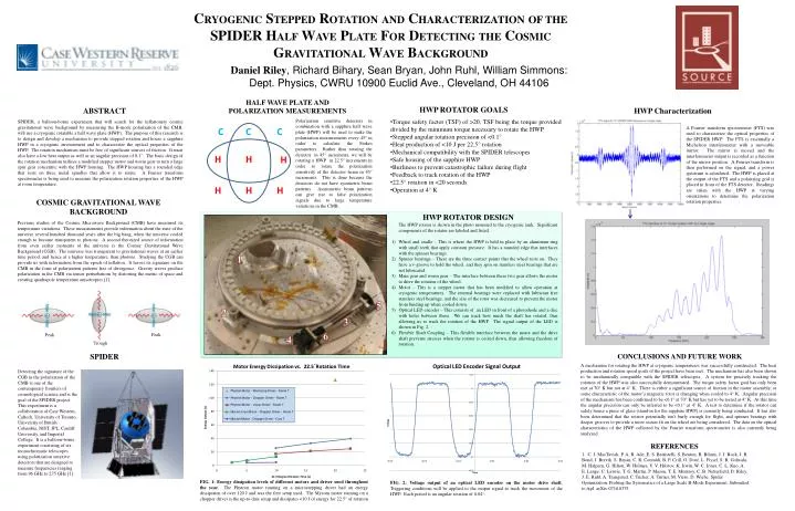
HWP ROTATOR DESIGN COSMIC GRAVITATIONAL WAVE BACKGROUND HWP ROTATOR GOALS HALF WAVE PLATE AND POLARIZATION MEASUREMENTS The HWP rotator is shown in the photo mounted to the cryogenic tank. Significant components of the rotator are labeled and listed. Wheel and cradle – This is where the HWP is held in place by an aluminum ring with small teeth that apply constant pressure. It has a rounded edge that interfaces with the spinner bearings. Spinner bearings – These are the three contact points that the wheel rests on. They have a v-groove to hold the wheel, and they spin on stainless steel bearings that are not lubricated. Main gear and worm gear – The interface between these two gear allows the motor to drive the rotation of the wheel. Motor – This is a stepper motor that has been modified to allow operation at cryogenic temperatures. The internal bearings were replaced with lubricant free stainless steel bearings, and the size of the rotor was decreased to prevent the motor from binding up when cooled down. Optical LED encoder – This consists of an LED in front of a photodiode and a disc with holes between them. We can track how much the shaft has rotated, thus allowing us to track the rotation of the HWP. The signal output of the LED is shown in Fig. 2. Flexible Shaft Coupling – This flexible interface between the motor and the drive shaft prevents stresses when the rotator is cooled down, thus allowing freedom of rotation. HWP Characterization ABSTRACT • Torque safety factor (TSF) of >20, TSF being the torque provided divided by the minimum torque necessary to rotate the HWP • Stepped angular rotation precision of <0.1° • Heat production of <10 J per 22.5° rotation • Mechanical compatibility with the SPIDER telescopes • Safe housing of the sapphire HWP • Burliness to prevent catastrophic failure during flight • Feedback to track rotation of the HWP • 22.5° rotation in <20 seconds • Operation at 4° K SPIDER, a balloon-borne experiment that will search for the inflationary cosmic gravitational wave background by measuring the B-mode polarization of the CMB, will use a cryogenic rotatable a half wave plate (HWP). The purpose of this research is to design and develop a mechanism to provide stepped rotation and house a sapphire HWP in a cryogenic environment and to characterize the optical properties of the HWP. The rotation mechanism must be free of significant sources of friction. It must also have a low heat output as well as an angular precision of 0.1˚. The basic design of the rotation mechanism utilizes a modified stepper motor and worm gear to turn a large spur gear concentric with the HWP housing. The HWP housing has a rounded edge that rests on three metal spindles that allow it to rotate. A Fourier transform spectrometer is being used to measure the polarization rotation properties of the HWP at room temperature. Polarization sensitive detectors in combination with a sapphire half wave plate (HWP) will be used to make the polarization measurements every 45° in order to calculate the Stokes parameters. Rather than rotating the detector in 45° increments, we will be rotating a HWP in 22.5° increments in order to rotate the polarization sensitivity of the detector beam in 45° increments. This is done because the detectors do not have symmetric beam patterns. Asymmetric beam patterns can give rise to false polarization signals due to large temperature variations in the CMB. Previous studies of the Cosmic Microwave Background (CMB) have measured its temperature variations. These measurements provide information about the state of the universe several hundred thousand years after the big bang, when the universe cooled enough to become transparent to photons. A second theorized source of information from even earlier moments of the universe is the Cosmic Gravitational Wave Background (CGB). The universe was transparent to gravitational waves at an earlier time period, and hence at a higher temperature, than photons. Studying the CGB can provide us with information from the epoch of inflation. It leaves its signature on the CMB in the form of polarization patterns free of divergence. Gravity waves produce polarization in the CMB via tensor perturbations by distorting the metric of space and creating quadrapole temperature anisotropies [1]. A Fourier transform spectrometer (FTS) was used to characterize the optical properties of the SPIDER HWP. The FTS is essentially a Michelson interferometer with a moveable mirror. The mirror is moved and the interferometer output is recorded as a function of the mirror position. A Fourier transform is then performed on the signal, and a power spectrum is calculated. The HWP is placed at the output of the FTS and a polarizing grid is placed in front of the FTS detector. Readings are taken with the HWP at varying orientations to determine the polarization rotation properties. CRYOGENIC STEPPED ROTATIONAND CHARACTERIZATIONOF THE SPIDER HALF WAVE PLATE FOR DETECTINGTHE COSMIC GRAVITATIONAL WAVE BACKGROUND e- e- e- Peak Daniel Riley, Richard Bihary, Sean Bryan, John Ruhl, William Simmons: Dept. Physics, CWRU 10900 Euclid Ave., Cleveland, OH 44106 Trough Peak 1 5 2 3 6 4 SPIDER CONCLUSIONS AND FUTURE WORK A mechanism for rotating the HWP at cryogenic temperatures was successfully constructed. The heat production and rotation speed goals of the project have been met. The mechanism has also been shown to be mechanically compatible with the SPIDER telescopes. A system for precisely tracking the rotation of the HWP was also successfully demonstrated. The torque safety factor goal has only been met at 70° K but not at 4° K. There is either a significant source of friction in the motor assembly, or some characteristic of the motor’s magnetic rotor is changing when cooled to 4° K. Angular precision of the mechanism has been confirmed to be <0.1° at 70° K but has yet to be tested at 4° K. At this time the angular precision can only be inferred to be <0.1° at 4° K. A test to determine if the rotator can safely house a piece of glass (stand-in for the sapphire HWP) is currently being conducted. It has also been determined that the rotator potentially isn’t burly enough for flight, and spinner bearings with deeper grooves to provide a more secure fit on the wheel are being considered. The data on the optical characteristics of the HWP collected by the Fourier transform spectrometer is also currently being analyzed. Detecting the signature of the CGB in the polarization of the CMB is one of the contemporary frontiers of cosmological science and is the goal of the SPIDER project. This experiment is a collaboration of Case Western, Caltech, University of Toronto, University of British Columbia, NIST, JPL, Cardiff University, and Imperial College. It is a balloon-borne experiment consisting of six monochromatic telescopes using polarization sensitive detectors that are designed to measure frequencies ranging from 96 GHz to 275 GHz [1]. REFERENCES 1. C. J. MacTavish, P. A. R. Ade, E. S. Battistelli, S. Benton, R. Bihary, J. J. Bock, J. R. Bond, J. Brevik, S. Bryan, C. R. Contaldi, B. P. Crill, O. Doré, L. Fissel, S. R. Golwala, M. Halpern, G. Hilton, W. Holmes, V. V. Hristov, K. Irwin, W. C. Jones, C. L. Kuo, A. E. Lange, C. Lawrie, T. G. Martin, P. Mason, T. E. Montroy, C. B. Netterfield, D. Riley, J. E. Ruhl, A. Trangsrud, C. Tucker, A. Turner, M. Viero, D. Wiebe. Spider Optimization: Probing the Systematics of a Large Scale B-Mode Experiment. Submitted to ApJ. arXiv:0710.0375 FIG. 1: Energy dissipation levels of different motors and driver used throughout the year. The Phytron motor running on a microstepping driver had an energy dissipation of over 120 J and was the first setup used. The Mycom motor running on a chopper driver is the up-to-date setup and dissipates <10 J of energyfor 22.5° of rotation FIG. 2: Voltage output of an optical LED encoder on the motor drive shaft. Triggering conditions will be applied to the output signal to track the movement of the HWP. Each period is an angular rotation of 0.04°.