Download
1 / 85
890 likes | 1.17k Views
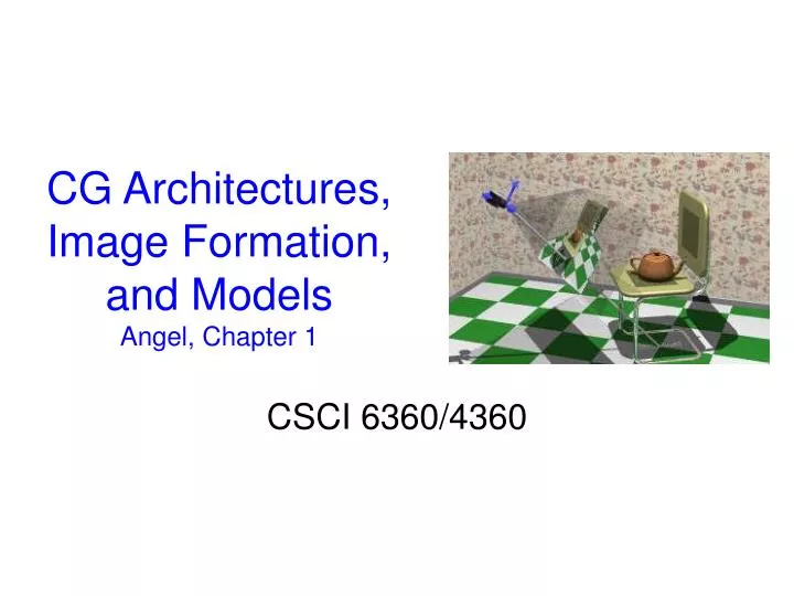
CG Architectures, Image Formation, and Models Angel, Chapter 1. CSCI 6360/4360. Elements of Computer Graphics. User, i.e., Human. “Interaction”. “Perception”. “Information”. Recall …. Display. An illusion:. analog world. represented. digitally. Elements of Computer Graphics.

E N D
CG Architectures, Image Formation, and ModelsAngel, Chapter 1 CSCI 6360/4360
Elements of Computer Graphics User, i.e., Human “Interaction” “Perception” “Information” Recall … Display An illusion: analog world represented digitally
Elements of Computer Graphics User, i.e., Human Open “Interaction” “Perception” “Information” System Display Closed System An illusion: analog world represented digitally Programming systems -windows -graphics Programming is a craft Hardware and graphics engines Lights Drawing 3-D Transformation Rendering Algorithms Viewing Representation of curves and surfaces “Models”, (Foley et al. term)
Elements of Computer Graphics User, i.e., Human Open “Interaction” “Perception” “Information” System Display Closed System An illusion: analog world represented digitally Programming systems -windows -graphics Programming is a craft Hardware and graphics engines Lights Drawing 3-D Transformation Rendering Algorithms Viewing Representation of curves and surfaces “Models”, (Foley et al. term)
Overview • “more later” … about all of what we’ll talk about tonight! • Angel’s “top down” (“gentle”) presentation • CG System Hardware Overview • But, how do you get a pixel on the display? • Images and Image Formation • Pinhole Camera • Human visual system • And a bit of depth to illustrate how an expert might exploit known elements • CG Programming Framework and Architecture • Pipeline architectures • OGL and the synthetic camera
CG Hardware System Overview • Components of a CG system • Raster displays • Display devices: crt, etc. • CG system architectures • GPU • Frame buffers • Addressability and resolution • “Scanning out” the image • Color look up tables • Input devices
Basic Graphics System pretty basic, Angel … note frame buffer Output device Input devices Image formed in FB
Conceptual (Programming) Framework for Interactive Computer Graphics • Overview – much more detail in 2nd half of class • Application program • maps application objects to views (images) of those objects by calling on graphics library • Graphics library/package (e.g., OpenGL) • is intermediary between application and the display hardware • User interaction • results in modification of model and/or image • Images • are usually means to an end: synthesis, design, manufacturing, visualization, ...
Raster Architecture (last time) • Early systems • Used part of system memory (system address space) for frame buffer • Single CPU set frame buffer and performed “graphics system” commands • Current systems • Separate processor gets cmds from CPU • Graphics Processing Unit (GPU) • “In hardware” • Scan conversion • Texturing • Dedicated texture memory • Lighting calculations • 3D transformation calculations • GPU more power than CPU • Interesting implications!
Current Graphics Workstations • Historically, small volume, high memory systems were necessary and expensive to do computer graphics defined as some frame rate with some number of polygons • Now, PC + high performance graphics card works fine for most applications • Coprocessor + large, multiple frame buffers • Not “hard line” between “workstations” and “pcs”
Current GPU – “Quick Look”, 1Where we’re going tonight • GPU architecture • Note cpu – gpu boundary • Will talk about “graphics pipeline” shortly
Current GPU – “Quick Look”, 2A complete architecture, FYI • GPU architecture detail • Gee whiz … • Nvidia … • But there is a frame buffer in there! • Also, note vertex and fragment processing
Graphics Display HardwareHistory, for completeness • Two classes of output technology • Vector (calligraphic, stroke, randomscan) • Still used in some plotters • Historical • Raster (TV, bitmap, pixmap), • Used in displays and laser printers • “dots” • Picture elements - pixels
Vector Architecture • Historic in interactive displays • However, useful in understanding some, now, software terminology • Vector display works with a display list/file stored in refresh buffer • Display controller draws all vectors at < 60 Hz • often at variable rate • flicker is a problem
Raster Definitions • Raster • A rectangular array of points or dots • Pixel (or, arcanely, Pel) • One dot or picture element of the raster • Scan Line • A row of pixels • Called that because in a crt an electron stream is moved across (scans) the crt face
Frame Buffer – “Memory Mapped” • Image, i.e., what shown on display, exists as way memory values set in frame buffer • Image “mapped” to memory • (supposed to be house and tree) • In practice, not 0’s and 1’s • “Frame buffer”, “refresh buffer” • like “frame” of a movie • Represents image, • what shows up on display • “Buffer” is a term for memory • Hence, “frame buffer” • Simple electronic process goes through (scans) this memory and control output device • Video – scan - controller • “scan out the image”
BTW - Addressability and Resolution (1,1) (9,7) • Fairly straightforward mapping of memory to display • Addressability • Number of individual dots per inch that can be created • May differ in horizontal and vertical • Resolution • Number of distinguishable lines per inch that a device can create • Closest spacing at which adjacent black and white lines can be distinguished • In fact, resolution usually less than addressability • Smooths out jaggies, etc.
“Scanning out the Image”, Overview • Again, frame buffer holds memory values representing pixel values • Scan controller goes through memory locations
FYI - Scanning out Image, Details • 1bit Bilevel Display • Recall, frame buffer holds value for display • Color, intensity • Simplest • Black and white (or any 2 colors) • 1000 x 1000 display needs 1,000,000 bits or 128k memory (8 bits/byte) • Memory access time > display time, so fetch chunks and control with registers • 1024x1024 memory 15 nanosec/pixel => 32 pixel chunks stored in shift registers/buffers • Digital intensity value -> Digital to Analog Conversion (DAC) ->analog signal to drive display
Frame Buffer “Depth” • 1 bit • For 2 levels • Display is 0-off or 1-on • 4 or 8 bits • For 16 levels or 256 levels of intensity (gray) • Gun is varied in intensity • 00-off … • 0011-gray … • 1111-bright • Also, 3 bits • For 8 levels • Or color look up table • Provides index into table of colors
Frame Buffer “Depth”“True Color” • 24 bits • “True color” • Enough eye can’t distinguish • > 24 bits • True color + • Fog • Alpha blending • Text overlay • … • In general, n-bits / pixel • Total frame buffer memory required • Addressability x depth • E.g., 1000 x 1000 x 24-bits = 3 mb • Also, Multiple frame buffers for animation, etc. • Currently, large amounts of graphics memory used for textures for texture mapping, etc.
OpenGL Buffers • Will consider buffers in detail later • Buffer depth typically a few hundred bits and can be much more • Color, and double buffering • Front: from which image is scanned out • Back: “next” image written into • 2 x 32-color + 8-alpha • Depth • Hidden surface removal using z-buffer algorithm • 16 min, 32 for fp arithmetic • Color indices • Lookup tables • Accumulation • Blending, compositing, etc. • Pixel at mi, njis all bits of the k bit-planes
FYI - Color Lookup Table, 1 • Display hardware may not have sufficient capacity (memory) to store all, e.g, cell phone • So, choose some to store • e.g., lots of shades of blue for water or sky (and not too many green) • Any specific 2n colors may not be adequate • (n typically 1624 in lowend systems) • Lookup table allows 2n colors out of 224 to be used in one picture, • some other 2n in another picture • Color table is a resource managed (usually) by window manager
FYI - Color LookUp Table, 2 • Pixel value is indexed to color look up table (CLUT) where color is stored. • Here use only 12 bits (4bits per color) for clarity typically, 24bits are used • CLUT look up done at video rates, overlapped with fetch and DAC • In 24bit ``true''color systems, 3 x 8 bits for R, G, B; each color has its own 8bit CLUT (0255) • CLUT allows variety of effects • pseudo coloring (LandSat images, stress diagrams, thermograms...) • fast image changes: change table rather than stored image • multiple images: select or composite/blend
Display Technologies …. Briefly: • Cathode ray tube • Monochrome • Color • LCD • Solid State • Active matrix • Plasma, projection, etc.
Cathode Ray Tube • Obsolete, but cg terms from • Electron gun emits stream of electrons • Accelerated toward phosphor-coated screen by high positive voltage at face of tube • Forced into narrow stream and directed at a point by focusing system • Intensity controlled, also • Electron hitting face of screen causes phosphor to emit visible light • Decays, and must be refreshed > 60 times/sec • “Flicker” results when eye can no longer fuse the (many) images • Critical Fusion Frequency • Typically 60 times/sec for raster displays • Varies with intensity, individuals, phosphor persistence, lighting, …
Scanning – for CRT Display • Interlaced scanning • Assume can only scan 30 times/sec • To reduce flicker, divide frame into two “fields” (odd and even lines) • Terminology • Vertical sync pulse • Signals the start of the next field • Vertical retrace • Time needed to get from the bottom of the current field to the top of the next field • Horizontal sync pulse • Signals the start of the new scan line • Horizontal retrace • Time needed to get from the end of the current scan line to the start of the next scan line.
Color CRT • Single electron gun for monochrome • Color seen depends on color of phosphor • Multiple electron guns for color • Shadow mask • Phosphors arranged in triads • Each triad has one R/G/B phosphor dot • Typically 2.3 to 2.5 triads per pixel • Shadow mask has one small hole for each phosphor triad • Aperture grill • i.e. Sony Trinitron • Phosphors arranged in vertical stripes • Shadow mask is a vertical “grill”
Liquid Crystal Display • 6 layers • Vertical polarizer plate • Layer with thin vertical grid wires electrodeposited on the surface adjoining the crystals • Thin liquid-crystal layer • Layer with horizontal grid wires • Horizontal polarizer • Reflector • Liquid-crystal material - long crystalline molecules, normally in spiral arrangement • Address x, y point with voltage • Causes molecules to align • Polarizing effect of crystal lost at this point • So, “dark spot” appears
FYI - Flat-Panel Displays • Emissive versus nonemissive • Emissive • Plasma panels • mixture of gases between two glass plates • vertical and horizontal conducting ribbons • apply voltage to two ribbons to make plasma glow • Thin-film electroluminescent displays similar, but phosphor instead of gas • LED's • matrix of diodes, one per pixel • apply voltage and they produce light • Nonemissive • LCD • LC substance flow like a liquid, but have crystaline molecular structure • Usually use nematic LC's (threadlike) • Two polarizers, two conductors, reflector • LC in normal state twists the light, so is reflected back to viewer • apply voltage to conductors to turn off (see figure) • Active Matrix LCD - transistor at each pixel (stores)
FYI - Stereoscopic Viewing • Compelling affect! • But, ergonomics challenges to apply • “promise of the future … always has been always will be” ??? • Left and right eyes get different images • Change in eye separation with depth • But, only perceive one image • Perceptual processes integrate different views from the two eyes • E.g, LCD Shutter Glasses • >120 hz monitor refresh • Different images on odd and even • LCD “Shutters” open and close for left and right eyes • (used to be metal shutters!)
Input: Logical and Physical DevicesAngel and interaction terminology • Locator • Logical: position and/or orientation • Physical: Tablet, mouse, trackball, touch panel, Light pen • Keyboard • Logical: characters and strings • Physical: Alphanumeric keyboard (coded or unencoded) • Valuator • Logical: single values in the space of real numbers • Physical: Rotary dials (bounded or unbounded), sliders • Choice • Logical: select from a set of actions or choices • Physical: Function keys
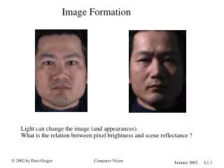
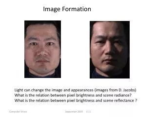
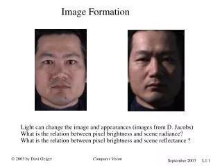
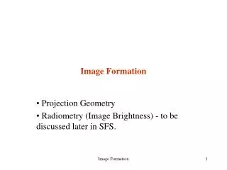
Images and Image Formation • Objects and viewers • Lights and Images • Image formation models • Physical systems • Pinhole camera • Human visual system • A bit of example detail to illustrate how knowing about human system is useful in computer graphics • None in Angel
Images and Image Formation • Physical (real or physical world) images have been “captured” for some time now … • Optical systems: • Cameras, telescopes, microscopes • Human visual system • Synthetic (synthesized, artificial) images may or may not exist • Can be created by computer, painting (through human imagination), etc. • Methods for creating computer images, especially in “real time” - which allows fully interactive computer graphics: • In some ways similar to optical methods, e.g., camera model and viewing • … and in other ways not! … • computationally tractable shading, discrete approach in general • Goals and techniques of interactive cg and photorealistic cg often differ • “good enough” is good enough
Image Formation: Objects and Viewers • Image formation process (either physical or mathematical abstraction) requires: • Object • Exists in a space independent of any image-formation process or viewer • Viewer • Physical • camera, human, • Abstractly, mathematically • location, orientation • In cg can specify synthetic objects as primitives with attributes and positions in space • Line: end points (vertices) and color • Sphere with some radius and segmentation • CAD systems provide an interface to facilitate construction of synthetic model of the (physical) world • OpenGL next chapter to do such things glBegin(GL_POLYGON) glvertex3f(0.0, 0.0, 0.0) /* vertex A */ glvertex3f(0.0, 1.0, 0.0) /* vertex B */ glvertex3f(0.0, 0.0, 1.0) /* vertex C */ glEnd();
Image Depends on Location(s) • Viewer forms the image • Image formed depends on perspective (“viewing angle”, …) of image • Formed on film, retina • Or in cg system • Different viewers form different images • (or same viewer from different location) • Of course, the image formed (even of a three-dimensional object) is two-dimensional • Film plane, retina are 2-d • This formation/mapping of three dimensions to two dimensions is one of the fundamental challenges of computer graphics
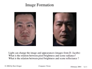
Lights and Images • Again of course, without light there would be no image! • Image formed (physically) by changing chemicals on film, exciting neurons, etc. • Light from a light source strikes various surfaces of the object • A portion (very small in fact) of the light striking the surfaces is reflected to the viewer, e.g., camera • Details of the interaction between light and surfaces of object determine how much (and what color, etc.) light enters camera • Light is a form of electromagnetic radiation • Visible (to humans) spectrum • Geometric optics models light sources as emitters of light energy, each with a fixed intensity • Point sources are typically used
Image Formation Models • Multiple approaches to how form images from set of objects • Using also properties of light sources and light-reflecting properties of the objects • E.g., ray tracingimaging model might follow all rays emanating from a single point source • Like we said, not many would reach viewer • Ray tracing in essence “does it backwards” • Follows “rays” through pixels of display • Radiosity also a physically based technique • Time constraints of interactive cg precludes use of these and related techniques • However, used for photorealistic images, e.g., “global affects, including accurate shadows and reflection • Image formation techniques that are “fast” are focus in techniques we will look at in detail • And are those implemented “in hardware” • And so accessed reasonably efficiently by OpenGL
Imaging System: Pinhole CameraPhysical image formation • Box with small hole in one side • Expose film by uncovering hole • Assume oriented to z-axis, and a single ray of light enters • Film plane at distance d from hole – a single ray of light isn’t interesting, but many are! • Can use similar triangles to determine projection of any point outside camera on to film plane • “side” view • Down x-axis www.silverprint.co.uk/acc21.html -
Point Location and Projectors • Can use similar triangles to determine projection of any point outside camera on to film plane • “side” view • Down x-axis 1. Find y coordinate of the image yp • yp = - y / (z/d) 2. And use top view to find xp • xp = - x / (z/d) 3. Point (xp, yp, -d) is the projection of the point (x, y, z) • This idea is at core of cg techniques! -
Elements of Computer Graphics User, i.e., Human Just a little bit … “Interaction” “Perception” “Information” Display An illusion: analog world represented digitally
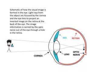
Imaging System: Human EyePhysical Reception • Mechanism for receiving light and transforming it into nerve transmissions • A transducer: light -> nerves • Light reflects from objects • Some strikes retina • Images are focused upside-down on retina • Ganglion cells (from brain!) detect pattern and movement • As camera, has: • equivalent of lens, aperture (pupil) • and film (retina) • Note – image upside down on retina • … perception!
Environment: Visible Light • Generally, the body’s sensory system is the way it is because it had survival value • Led to success • survival and reproduction • Focus on human vision (because of computer), but all share basic notions • Humans have receptors for (a small part of) the electromagnetic spectrum • Have receptors sensitive to (fire when excited by) energy 400-700nm • Snakes “see” infrared, some insects ultraviolet • i.e., have receptors that fire
Human Eye: Retinal Receptors • Two types of (photo) receptors on retina: rods and cones • Rods look like, well, rods … • Rods: • spread all over the retinal surface (75 - 150 million) • low resolution, no color vision, but very sensitive to low light (scotopic or dim-light vision) • Cones: • dense array around the central portion of the retina, the fovea centralis (6 - 7 million) • high-resolution, color vision, but require brighter light (photopic or bright-light vision)
FYI - Human Eye: Lens • Eye has compound lens: • cornea (power) and lens (adjust focal length) f = focal length of lens d = distance to object r = distance to image that is formed • Flexibility of lens changes with age, approaching 0 at 60 years
Human Eye: Depth of Field and Focus • Depth of focus • Distance over which objects are in focus without change in focus • Note: Different colors have different depths of focus – chromatic aberration • E.g., blue vs.red • Varies with size of pupil • Range of focus: Distance Near Far Depth of focus 50 cm 43 cm 60 cm 17 cm 1 m 75 cm 1.5 m 75 cm 2 m 1.2m 6.0m 1.8 m 3 m 1.5m Infinity Large • Rarely do computer systems model
Human Eye: Depth of Field - Example • Photographic Images: • Depth of field longer with small aperture (f stop) • Range of focus: Distance Near Far Depth of focus 50 cm 43 cm 60 cm 17 cm 1 m 75 cm 1.5 m 75 cm 2 m 1.2m 6.0m 1.8 m 3 m 1.5m Infinity Large
Most people see red Closer than blue