Download
1 / 28
280 likes | 287 Views
Protocol Technology. Common Channel Signaling System 7 (SS7) Part 1. Gusztáv Adamis BME TMIT 20 1 6. Channel Associated Signaling - CAS. Signaling : set-up and release of connections between two subscribers

E N D
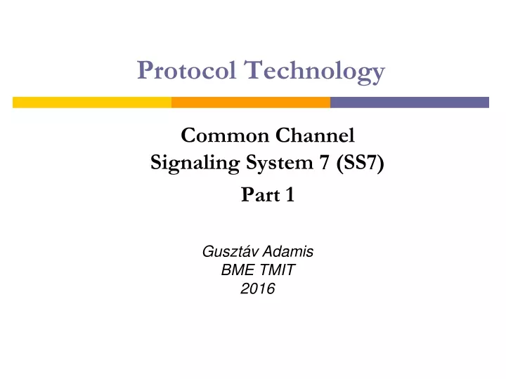
Protocol Technology CommonChannelSignaling System 7 (SS7) Part 1 Gusztáv Adamis BME TMIT 2016
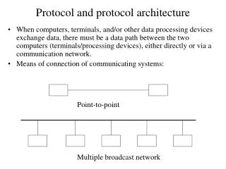
Channel Associated Signaling - CAS • Signaling: set-up and release of connections between two subscribers • Signals were carried by the same circuit (subscriber line, trunk) that carried the speech during the call • Subscriber Signaling – between subscriber and his local exchange • Not possible to send signaling messages in absence of a call
Common Channel Signaling - CCS • CCS • Signaling does not have to go along the same path as speech • Abbreviated as CCS7, CCS#7, SS7 or simply C7 • Modular in design of protocol architecture • Non call related signaling possible
dr. Adamis Gusztáv Common Channel Signaling Systems • Digital signals on a network that is independent from voice circuits • One signaling link serves the need of several voice circuits • Disadvantages: • additional subnetwork plus cost • more complicated switches • explicit call continuity check may be needed • Advantages: • better voice circuit utilisation • complex messages: several services/features can be controlled by one signaling system • higher reliability than for voice transmission • call-independent messages possible • data base query • SMS • operation and mainteneance messages
CCSS Circuit Voice Network Link Signaling (Transfer) Point SP SP Signaling Network SP STP
CCSS Circuit Voice Network SCP OAM HLR … Link Signaling (Transfer) Point SP SP SP Signaling Network SP STP
Connection Types • Associated connection • Same path for link and circuit • different, dedicated time slots • different, dedicated cables • Quasi-associated connection • Different paths
dr. Adamis Gusztáv CCSS7 Subnetwork
CCSS7 Protocol Architecture Call Control Services Transaction services OSI layers MAP, INAP + TCAP ISDN User Part (ISUP) Level 4 Telephone User Part (TUP) Level 4 4 - 7 SCCP 3 MTP 1 - 3 2 1
SS7 Protocol Layers Signaling System 7 was introduced by AT&T in 1975 and approved by worldwide standard bodies in 1980. SS7 basic functions are as follows MTP (Message Transfer Part) - Provides a reliable transfer and delivery of signaling information in a signaling network. TUP (Telephone User Part) - Provides the transport of call set-up information between two signaling points only for voice services. ISUP (ISDN User Part) - Provides the transport of call set-up information between two signaling points. SCCP (Signaling Connection Control Point) - Provides additional routing capabilities via SubSystem Numbers (SSNs). It also offers the capability of routing based on dialed digits or global title translation. TCAP (Transaction Capability Application Part) - Provides the capability of transferring non-circuit-related information between signaling points. ----------------------- SCTP (Streams Control Transmission Protocol) - Provides generic transport for SCN signaling . M2PA (MTP 2 Peer-to-peer Adaptation Layer) - Enables SS7 links replacement over IP. M2UA (MTP 2 User Adaptation Layer) - Enables SS7 back-hauling from remote end-points over IP. M3UA (MTP 3 User Adaptation Layer) - Enables SS7 User Parts (e.g. ISUP and SCCP) to run over IP. SUA (SCCP User Adaptation Layer) - Enables SS7 Application Parts (e.g. TCAP) to run over IP.
MTP levels of CCSS7 Level 3 Signaling Message Handling + Signaling Network Management Message Transfer Part (MTP) Level 2 Data Link Control Level 1 Physical Connections
Message Transfer Part (MTP) • Level 1 Physical Connections : Definesthephysical, electrical, and functionalcharacteristics of thedigitalsignaling link. Definedphysicalinterfacesinclude, DS1 (1.544 Mbps), E1 (2.048 Mbps), V.35 (64 kbps),DS0 (64 kbps), and DS0A (56 kbps). • Level 2 Data Link Control : Definesthefunctions and procedurestoensurethatmessagesarereliablytransmittedacross a signaling link. Theyimplement flow control, messagesequencevalidation, and errorchecking. When an erroroccurson a signaling link, themessagesareretransmitted. • Framing • Errordetection and correction • Differentmessagetypes
MTP-2 Message Structure • Flag: 01111110 + bit stuffing • FSN/BSN: Forward/Backward Sequence Number • FIB/BIB: Forward/Backward Indicator Bit • LI: Length Indicator • CK: Checksum • FISU: Fill-In Signal Unit • LSSU: Link Status Signal Unit • MSU: Message Signal Unit • SIF: Service Information Field („Address” + Message) • SIO: Service Information Octet
A B FSN,FIB BSN,BIB 1,0 2,0 1,0 positive ack. 3,0 2,0 X 4,0 2,0 5,0 2,1 6,0 negative ack. 2,1 3,1 2,1 4,1 3,1 positive ack. 5,1 4,1 MTP-2 – Basic Error Correction
Message Transfer Part (MTP) • Level 3 • Signaling Message Handling: Provides message routing between signaling points in a SS7 network. • Signaling Network Management: Monitors state of the signaling network + performs reconfiguration when necessary
Signaling Networks, Signaling Point Codes International Network Nemzetközi hálózat National Nemzeti Nemzeti National Network A hálózat A hálózat C Network C Nemzeti National National Nemzeti National Nemzeti Interconnecting összekötő Network B hálózat B hálózat D Network D hálózat Network Signaling Point Code – 14 bit ISPC = Zone Code + Area/Network Code + Signaling Point Identifier NISPC NSPC
MTP-3 Addressing • RL – Routing Label • OPC, DPC – Originating Point Code, Destination Point Code – • SLS – Signaling Link Selection • SIO – Service Indicator Octet = Network Indicator (NI) + Service Indicator (SI) RL SIO OPC DPC SLS 4 bit 14 bit 14 bit 8 bit
UPs MTP-3 Signaling Links Sign. Mess. Sign. Mess. distribution discrimination SNM MTP-2 ISUP SCCP Sign. Mess. routing MTP-3 Signaling Message Handling
Signaling Route Management Jelzésútvonal menedzselés Jelzésútvonal menedzselés Signaling Traffic Management Changeover Át kapcsolás Changeback Vissza - Route Availability Control kapcsolás Forced Rerouting Kényszerített átirányítás UP UP Vezérelt átirányítás Újraindítás Restart Link Availability Control Szakasz használhatóság vezérlés Sign. Traffic Flow Ctrl. Jelzésforgalom folyam vezérlés Signaling Link Management Jelzésszakasz menedzselés MGMT (operator) MTP2 MTP-3 Signaling Network Management Controlled Rerouting
Protocol stack for fixed networks in CCSS7 Call Control Messages ISUP ISUP Transport of Signaling Level 3 Level 3 Messages within one network MTP Data Link Control Level 2 Level 2 Physical Connections Level 1 Level 1 MTP – Message Transfer Part
User Parts • Telephone User Part (TUP) • Defines the international telephone call control signaling functions for basic call setup and release. Withdrawn. • Data User Part (DUP) • Defines data transfer control. Obsolete. • ISDN User Part (ISUP) • Defines the protocol used to setup, manage, and release trunk circuits that carry voice and data + ISDN Supplementary Services • Call Control • Circuit Supervision
ISUP Functional Blocks Switch Call Processing Control Circuit Supervision Control Message Sending Control Message Distribution Control
ISDN call establishment – early ACM DSS1 ISUP DSS1 ISDN switch ISDN equipm. ISDN equipm. ISDN switch SABME UA I (Setup) I (Setup Ack) I (Information) I (Call Proceeding) IAM UI (Setup) ACM SABME UA I (Setup Ack) I (Alert) CPG Ringing I (Alert) Ringing tone I (Connection) ANM Answer I (Connection) I (Conn. Ack.) I (Conn. Ack.) B channel connection
ISDN call establishment – late ACM DSS1 ISUP DSS1 ISDN switch ISDN equipm. ISDN equipm. ISDN switch SABME UA I (Setup) I (Setup Ack) I (Information) I (Call Proceeding) IAM UI (Setup) SABME UA I (Setup Ack) I (Alert) Ringing ACM I (Alert) Ringing tone I (Connection) ANM Answer I (Connection) I (Conn. Ack.) I (Conn. Ack.) B channel connection
ISDN call release ISDN equipm. ISDN equipm. ISDN switch ISDN switch DSS1 ISUP DSS1 B channel connection I (Disconnect) REL Dis- connect I (Disconnect) I (Release) RLC I (Release) I (Rel. Complete) I (Rel. Complete) DISC DISC UA UA
ISUP messages • Initial address message (IAM): contains all necessary information for a switch to establish a connection • Subsequent Address Message (SAM) • Address complete message (ACM): acknowledge to IAM; the required circuit is reserved and the “phone is ringing” (ringback tone) • Call Progress (CPG) • Answer message (ANM): occurs when the called party picks up the phone • Release (REL): sent by the switch indicating that the phone hung up(Parameter: reason) • Release complete (RLC): acknowledges receipt of REL
IAM parameters General info Signaling requirements Type of caller Voice line (B channel) requirements