Download
1 / 24
240 likes | 350 Views
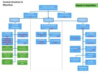
Dark Current Simulation for the T18vg2.6 Structure. Zenghai Li , Arno Candel, Lixin Ge SLAC National Accelerator Laboratory CLIC Workshop, Oct 14, 2009, CERN. * Work supported by U.S. DOE ASCR, BES & HEP Divisions under contract DE-AC02-76SF00515. Outline. T18vg2.6 Dark Current Simulation

E N D
Dark Current Simulation for the T18vg2.6 Structure Zenghai Li, Arno Candel, Lixin Ge SLAC National Accelerator Laboratory CLIC Workshop, Oct 14, 2009, CERN * Work supported by U.S. DOE ASCR, BES & HEP Divisions under contract DE-AC02-76SF00515
Outline • T18vg2.6 Dark Current Simulation • Dark current spectrum vs measurement • Field emitter modeling • PIC simulation of emitter emission (Arno’s talk) • Emitter heating due to emission current • Emitter heating due to RF field enhancement
T18vg2.6 Structure • Structure being tested at KEK and SLAC • Simulation Code: (ACE3P) • S3P - S-Parameter & Fields • Track3P - Particle Tracking
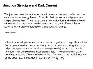
T18 Structure Fields • RF fields obtained using S3P with surface loss • S11=0.014; S22=0.032; S12=0.82 Bs Es Structure tapered: higher E fields at output end Higher B field at the output end, not as significant as E field
Dark Current Simulation Using Track3P Dark Current Simulation • Fowler-Nordheim field emission • Secondary Electrons • Analyze accumulated effects of DC current & power
Dark Current Emitter Simulation • Intercepted electrons - dark current heating on surface • Deposit energy into the wall results in surface heating • Captured electrons: energy spectrum • Emitter (disk) location - energy • Emitter density on disk – amplitude • Heating on dark current emitter • Due to emission current • Due to RF field enhancement on emitter Emitted from iris #6
Dark Current vs RF Heating Dark Current Heating • Impact concentrated in high E region around iris • Impact energy could be as high as a few MeV • Depth of energy deposit ~ 1-2 hundred microns • Significantly higher heating power at output end RF Pulse Heating • High on outer wall where E field is “low”. • Depth ~ skin depth • Temperature rise is around 250C at 100MV/m, 200ns pulse length • At Eacc=80 MV/m; (Hs/Ea~0.004), Power_max=1.4 GW/m2 Dark Current Heating distribution Assumed emitters uniformly distributed. In reality, most likely clusters of emitters, result in local hot spots. RF Heating distribution
High Power Test Data - Breakdown Distribution F. Wang KEK, Higo, Doebert Red: real cell timing Blue: linear cell timing • Breakdown rate significantly higher at the output end • Good correlation with field enhancement and dark current heating at the output end
Dark Current Measurement & Simulation Faraday Cup to measure dark current Dipole (dP/P) Schematic of KEK high power test and dark current measurement dE/E filter slit Simulation “schematics”
T18_VG2.4_Disk_#2Dark current spectra measured 18 June 2009 Dependence on power Dependence on width Measurement Data at KEK (Higo) Higo 090703
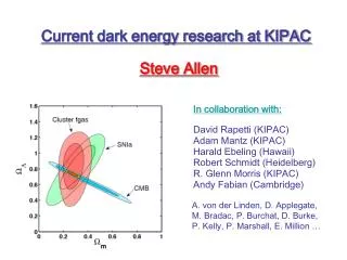
Dark Current Spectrum Comparison Measured dark current energy spectrum at downstream Simulation Eacc=97MV/m. dE/E=0.1, zbp=2.9m Differences? Measured dark current spectrum details would depend on the number of emitters on the disks
Heating Due to Dark Current Impact ? Disk 10 Disk 17 • Dark Current Collimation By Disk Iris. • Some electrons have very high impact energies.
Electron Impact Energy Emitted from disk 3 Emitted from disk 10 Emitted from disk 17
Impact Energy vs Emission Site Field E field determined amount of emission
Sharon Lee ICSE2006 Heating Due to Dark Current Impact • Field emission current density based on FN can be significant • with beta=50, Eacc=100 MV/m, • Jpeak ~1013 A/m2 • Need to study effects of individual emitters • PIC simulation of initial emitter phase space Colored by momentum • MeV energy electrons • Larger spot and deep depth • localized heating may not be as significant • Current may be much higher when breakdown is being developed? • site of future emitter? Emitter - micron or less in size
“Modeling” Of Field Emitters (C. Adolphsen) double tip cone asperities • Calculate field enhancement beta of emitter protrusion • PIC simulation: FN + self consistent space charge effect • Using a emitter shape with right beta vale (50 as measured) • Initial emitter phase space – impact heating distribution • Emission current - emission heating of emitter G. A. Mesyats /P. Wilson
Single Tip: Beta vs Shape Field contour plot Field enhancement beta vs tip elongate ratio and tip length
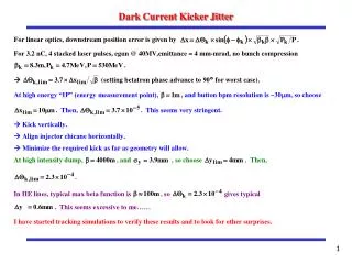
Field Emission Heating • Current is pulled out in ~ ± 40deg rf phase (FN model) • Field emission current density • Jpeak ~1013 A/m2 with beta=50, Eacc=100 MV/m • Need PIC to include space charge effects (Arno’s talk) • This current produce heating on emitter
Emitter Heating Due to RF • Emitter protrusion can produce significant surface magnetic field enhancement • May lead to higher local heating on emitter tip due to RF magnetic field
Heating On Emitter • Both RF and Emission (field+thermal) contribute to emitter heating • Larger cell iris – higher RF heating • Smaller iris (but high E) – higher emission heating • In high E region, strong E force pull the tip outward • may result in development of “sharp” emitters over time • lead to breakdown when dark current and dark current heating exceed threshold
NLC H60VG3S17 Structure Surface Field RF Heating • Peak Surface Field & Heating • Surface E field and RF heating higher at the output end • Most breakdowns in the front
NLC H60VG3S17 Structure • Surface field along disk contour • Disk 8 and 50 comparison (same acceleration gradient)
Summary • Progress being made in simulating CLIC T18 structures using Track3P. Dark current spectrum compared with measurement – which may provide information of field emission conditions of disks • Both RF and field emission contribute to emitter heating • High temperature plus strong E force pulling (of emitter tip) could lead to development of “sharp” emitters over time, may eventually reach breakdown threshold • Self consistent (space charge) emitter emission being performed using PIC to study emission heating • Surface field enhancement due emitter protrusion being calculated using Omega3P to study RF heating • Detailed of modeling of field emitters in progress