Download
1 / 26
260 likes | 383 Views
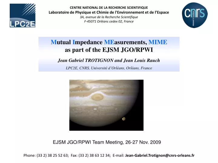
CENTRE NATIONAL DE LA RECHERCHE SCIENTIFIQUE Laboratoire de Physique et Chimie de l'Environnement et de l’Espace 3A, avenue de la Recherche Scientifique F-45071 Orléans cedex 02, France. M utual I mpedance ME asurements , MIME as part of the EJSM JGO/RPWI

E N D
CENTRE NATIONAL DE LA RECHERCHE SCIENTIFIQUE Laboratoire de Physique et Chimie de l'Environnement et de l’Espace 3A, avenue de la Recherche Scientifique F-45071 Orléans cedex 02, France Mutual Impedance MEasurements, MIME as part of the EJSM JGO/RPWI Jean Gabriel TROTIGNON and Jean Louis Rauch LPC2E, CNRS, Université d’Orléans, Orléans, France EJSM JGO/RPWI Team Meeting, 26-27 Nov. 2009 Phone: (33 2) 38 25 52 63; Fax: (33 2) 38 63 12 34; E-mail: Jean-Gabriel.Trotignon@cnrs-orleans.fr
EJSM JGO/RPWI Team Meeting, 26-27 Nov. 2009 Mutual Impedance MEasurements, MIME as part of the EJSM JGO/RPWI Presentation Outline Experiment Objectives Principle of Measurements Range of Measurements Heritage Instrument Conclusion Téléphone: (33 2) 38 25 52 63 Secrétariat: (33 2) 38 25 52 64 Télécopie (Fax): (33 2) 38 63 12 34 E-mail: Jean-Gabriel.Trotignon@cnrs-orleans.fr
JGO/RPWI/MIME Experiment Objectives (1 / 2) • Provide reliable/accurate measurements of totalplasma density & thermal electron temperature, in Jupiter system environment (solar wind included); • Contribute to the study of the interactions between solar wind & Jupiter’s Magnetosphere, in particular around Ganymède and Callisto; • Give insight into thermal coupling between neutral & charged particles; • Detect plasma boundaries and identify plasma regimes;
JGO/RPWI/MIME Experiment Objectives (2 / 2) • Enable selfand/ormutual impedancesof LP-PWI and possibly RA-PWI electric antennae to be determined as a function of plasma environment; • Determine the effective length of these antennae (then allow E-field component of waves to be calibrated); • Possibly measure the physical/deployed length of antennae; • Contribute to onboard calibrations of LP-PWI, and maybe SCM and RA-PWI (calibration signal can be delivered) cross-calibration between sensors.
MIME Principle of Measurements A sinusoidal signal of known amplitude & frequency, coming from a current (or voltage) generator, is applied to antenna probe or wire shield, by short pulses (some ms), while induced voltage (or current) is simultaneously measured. Antenna impedanceZ = V / I is a function of frequency & plasma conditions. Transmitted frequency varies step by step in a frequency bandwidth that includes the plasma frequency expected at Jupiter’s Magnetosphere (Ne proportional to Fpe2). Impedance spectra are computed onboard by FFT/DFT algorithms. Plasma parameters, such as density and electron temperature, are derived from variations of both impedance modulus and phase close to Fpe.
MIME Principle of Measurements (cont’d) • Thermal electron temperature Te shall be determined provided 2 λD < L < a few tens λD , where L is the tip-to-tip antenna length and the plasma λD Debye Length • For the total electron density Ne, L must be higher than λD and can be higher than a few tens λD depending on the onboard FFT frequency resolution • Ne can be determined from resonance and/or wave signatures at the plasma frequency Fpe, the upper-hybrid frequency Fuh and Berstein mode frequencies Fqn • As a bonus, the magnetic field strength B can be derived from the electron cyclotron frequency Fce and its gyroharmonics nFce • Ne (cm-3) = Fpe2 (kHz) / 81 • Fce (Hz) = 28 B (nT) • Fuh = (Fpe + Fce)1/2 • Fpe (kHz) = 6687 Te1/2 (eV) / λD(cm)
616 kHz Fuh 896 FQ2 1232 FQ3 266 kHz Interference 1624 FQ4 812 2Fce 1176 3Fce 406 kHz Fce 1568 4Fce 4 March 2005, 22:12:39.14 UT, 0 dB ≡ 0.6 μV Hz1/2 2,090 km altitude Fpe = 468 kHz = 1.17 Fce Ne = 2,700 cm-3
CENTRE NATIONAL DE LA RECHERCHE SCIENTIFIQUE Laboratoire de Physique et Chimie de l'Environnement et de l’Espace 3A, avenue de la Recherche Scientifique F-45071 Orléans cedex 02, France MIME Range of Measurements Phone: (33 2) 38 25 52 63; Fax: (33 2) 38 63 12 34; E-mail: Jean-Gabriel.Trotignon@cnrs-orleans.fr
Comparison between a 2 x 3 m long antenna (green) and a 2 x 1 m one (yellow); Ne and Te should be measured provided 0.5 cm ≤ λD ≤ 3 m (or 1 m)
Callisto (Gurnett et al., 2000) Ne ~ 400 cm-3 (180 kHz) at 535 km > 100 cm-3 (90 kHz) at 500 - 600 km Iomospheric peak: 7 000 – 17 000 cm-3 (750 – 1200 kHz) at 30-50 km Ganymede (Gurnett et al., 1996; Eviatar et al., 2001) Ne ~ 200 – 300 cm-3 (130 – 160 kHz) at 1 000 km Ne peak 400 - 2 500 cm-3 (180 – 450 kHz)
Expected MIME Range of Measurements • Frequency bandwidth: from a few hundred Hz* up to 3 MHz; • Debye length: from 0.5 cm up to 1-3 m (depending on antenna length); • Total plasma density: 0.01 – 1.5 105 cm-3; • Electron temperature: 0.01 – 100 eV. • The E-field antenna is assumed to be of the order of 2 to 6 m tip-to-tip long • (the longer, the better) * Lower-frequency signals can be produced for sensor calibrations (TBD)
CENTRE NATIONAL DE LA RECHERCHE SCIENTIFIQUE Laboratoire de Physique et Chimie de l'Environnement et de l’Espace 3A, avenue de la Recherche Scientifique F-45071 Orléans cedex 02, France Mutual Impedance Technique Heritage The mutual/self impedance measurement technique has successfully been used, during nearly three decades, onboard ionospheric rockets and spacecraft (GEOS, VIKING, MARS 96, ROSETTA, and more recently BepiColombo/MMO). Phone: (33 2) 38 25 52 63; Fax: (33 2) 38 63 12 34; E-mail: Jean-Gabriel.Trotignon@cnrs-orleans.fr
Mutual Impedance Technique Heritage (cont’d) Active: Impedance Modulus Passive: Natural waves Active: Impedance Phase ROSETTA/RPC/MIP Observations in the Earth’s Plasmasphere
Double probe Double probe Double wire-shield Double wire-shield Mutual Impedance Technique Heritage (cont’d) Numerical Simulations for BepiColombo/MMO Both the capacitance and the resistance of the MEFISTO antenna exhibit a peak at the plasma frequency (=> density) and a “plateau” below (=> temperature). Here, Debye length is 5 m, which is a typical value in solar wind close to Mercury (~30 m antenna tip-to-tip length).
CENTRE NATIONAL DE LA RECHERCHE SCIENTIFIQUE Laboratoire de Physique et Chimie de l'Environnement et de l’Espace 3A, avenue de la Recherche Scientifique F-45071 Orléans cedex 02, France MIME Instrument Phone: (33 2) 38 25 52 63; Fax: (33 2) 38 63 12 34; E-mail: Jean-Gabriel.Trotignon@cnrs-orleans.fr
command word digital signal generator signal controller () electric antenna(e) clock ADSP signal analyser (FFT, phase…) signal acquisition Global view of MIME instrument () also to SCM for calibrations (TBD)
Possible Electrical Interface: here AM²P-E to MEFISTO on BepiColombo/MMO Output signals of synthesizer are referenced to ground
Electrical Interfaces : MIME to E-Field Antenna(e) Detail of possible interface with E-Field antenna(e) for wire and mutual modes synthesizer MIME output switch Safety relay MIME Sensor Electronics E-Field Sensor
RPWI/MIME Elements • MIME may be composed of the following elements: • The electronic board hosted in RA (it would allow MIME to be connected to every electric/magnetic sensors); • Current probes hosted by E-field antenna deployment boxes (as in BepiColombo/MEFISTO ones); • EGSE including data processing software.
current injected on LP/PWI spheres, voltage is measured send calibration signal to a selected sensor: LP/PWI or SCM 3 cases voltageinjected on boom external shield, current/voltage is measured • V1 and V2 (2 channels) • V1 -V2 (1 channel) • I1 and I2 (2 channels) • I1 -I2 (1 channel) • V1 - V2 (1 channel) • I1 - I2 and V1 - V2 (2 channels) MIME possible working modes “I " measured by MIME current probe “V " measured by LP/PWI
MIME Measurement Point Definition • A MIME measurement point contains 3 pieces of information: • Reference spectrum (no transmission) • Power spectrum • Phase spectrum • from which Ne, Te, antenna impedances… are derived on ground. Note: to increase SNR, each frequency may be transmitted n times depending on MIME working modes, and averages will therefore be computed onboard.
MIME power and mass ressources (BepiColombo/MMO/AM2P) Mass: 13 g each Power consumption: 50 mW Size: 52 mm x 52 mm (Rosetta/MIP) Mass: 470 g (1.3 g / cm2) Power consumption: 1.3 W (1.6 W peak) Size: 247 mm x 147 mm (BepiColombo/AM2P) Mass: 240 g (0.8 g / cm2) Power consumption: 0.5 W (0.7 W peak) Size: A5
MIME Telemetry Ressources • Survey: 1952 bits / 60 s (33 bits s-1) • Ref. spectrum (passive): 64 frequency bins x 10 bits x 1 • Power spectrum: 64 frequency bins x 10 bits x 1 • Phase spectrum: 64 frequency bins x 10 bits x 1 • HK: 32 bits • Nominal: 6976 bits / 30 s (233 bits s-1) • Ref. spectrum: 96 frequency bins x 12 bits x 2 • Power spectrum: 96 frequency bins x 12 bits x 2 • Phase spectrum: 96 frequency bins x 12 bits x 2 • HK: 64 bits • Burst: 12 352 bits / 10 s (1 235 bits s-1) • Ref. spectrum: 128 frequency bins x 16 bits x 2 • Power spectrum: 128 frequency bins x 16 bits x 2 • Phase spectrum: 128 frequency bins x 16 bits x 2 • HK: 64 bits
E-Field Antenna Occupancy Example: N = 24 (frequency step repetition factor; for a high signal to noise ratio) Frequency sweep = 128 different frequency steps (FFT: 256 samples) 3 Frequency bands: 200 Hz – 20 kHz; 2 kHz – 200 kHz; 20 kHz – 2 MHz 1 or 2 acquisition channels Acquisition time (worst case): 855 ms (including time for the plasma to be stabilized) 1 MIME channel Ref F0 F1 F126 F127 Frequency repeated N times OR 2 MIME channels Ref F0 F1 F126 F127 Ref F0 F1 F126 F127 MIME emission 2 times shorter Frequency repeated N/2 times
CENTRE NATIONAL DE LA RECHERCHE SCIENTIFIQUE Laboratoire de Physique et Chimie de l'Environnement et de l’Espace 3A, avenue de la Recherche Scientifique F-45071 Orléans cedex 02, France Mutual Impedance MEasurements, MIME as part of the EJSM JGO/RPWI J. G. Trotignon and J. L. Rauch Conclusion Thank you, first, for the invitation to participate in this exciting mission; MIME may definitely contribute to the study of the Jupiter’ magnetosphere, in particular in measuring the electron plasma density and temperature, determining the effective length of electric antennae, helping out with in-flight sensor calibrations. Application for funding has been submitted to CNES. Phone: (33 2) 38 25 52 63; Fax: (33 2) 38 63 12 34; E-mail: Jean-Gabriel.Trotignon@cnrs-orleans.fr