Download
1 / 54
560 likes | 572 Views
Conditions of the Contract for Construction. AIA A 201 General Conditions Foundation Plans. Construction Documents & Contracts. AIA A201 - Introduction Purpose: A legal basis for constructing a project.

E N D
Conditions of the Contract for Construction • AIA A 201 General Conditions • Foundation Plans
Construction Documents & Contracts
AIA A201 - Introduction Purpose: A legal basis for constructing a project. Use: AIA A201 is the most widely used document for this purpose, especially in “private“ construction projects 2 Basic Things to Remember: • It is general and covers items that are common to every project. It must, therefore be tailored to meet the needs of a specific project by supplementary or special conditions. • It forms a part of the Owner-Contractor Agreement, which is a contract between those parties only. The architect is not a party to that contract and is not permitted to prepare it. Only an attorney is authorized to prepare such a contract. The architect should forward all legal contract forms to the owner. These documents must be reviewed by the owner’s attorney and incorporated into the project manual. Architects should never act unilaterally concerning general, supplementary or special conditions of the contract.
Standard Form of General Conditions The conditions of the contract establish the “rules” which are consistent from project to project. They deal with contractual matters not with procedural requirements (refer to Division 1). • Supplementary Conditions: Modify the standard forms, especially with multiple primes, fast-track & cost-plus-fee projects. • Relation to Local Codes & Laws: They override the General Conditions • Rights and Obligations of the Owner Implicit: Access to site & cooperation Explicit: $ contractor & furnish evidence, furnish documentation, copies id CD’s, hire his/her own forces or multiple contractors, stop the work for specific reasons (defective, not in accordance with CD’s, slow progress, does not correct mistakes), owner can make corrections using others. General Conditions assumes 1 prime or GC on the job
Major Elements of the General Conditions • Bonds: A form if insurance protecting the owner. Bonds are furnished by surety • Performance Bond – guarantees the contractor will perform the work in accordance with the CD’s. • Bid Bond - guarantees the bidder will sign an agreement; usually for 5%-10% of the bid amount the bond will compensate the owner for the $ difference. • Labor & Material Payment Bond - guarantees the contractor will pay all labor and material $
Major Elements of the General Conditions • Insurance • Owner • Builder’s risk (property) insurance for full cost of construction up to 100’ away; includes riders for theft, vandalism, etc. • Contractor • Worker’s Compensation - job injuries required by most States • Liability - claims for injuries, sickness & death • Contractual Liability - indemnification; hold harmless • *Personal Injury - slander, libel, false arrest • *Property - explosion, sudden collapse • *Auto
Major Elements of the General Conditions • Liens • Contractor, supplier or worker can force the sale of property to satisfy the claim ofnon-payment by the owner. • Liens encumber the owners title and effect their credit rating • Not permitted in public projects • Federal projects require material and labor bonds are per the Miller Act. • After each payment the owner may ask for aRelease of Liens for the amount of that payment
Major Elements of the General Conditions • Shop Drawings & Submittals • Responsibility of the Contractor • Prepare shop drawings based on verified field measurements, construction criteria; checked and coordinated drawings with a stamp; submit drawings, data & samples per specs. • Responsibility of the Architect • Review and “approve” or take other action on shop drawings • Architects DO NOT review un-stamped submittals • Architect's approval is for conformance to the contract documents only; the contractor is responsible for deviations even on architect approved submittals
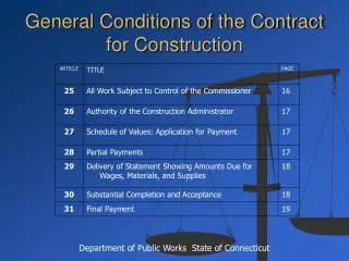
Major Elements of the General Conditions • Time Limits, Schedule & Delay • Work must be completed within the allotted # of days; liquidated damages & bonus clauses • Time extension for force majeure (Acts of God) • Payment Procedures • Contractor must submit a schedule of values • Contractor get money for mobilization and submittals • Contractor must submit payment application for architect certification (approval of rejection) • Site Safety
Major Elements of the General Conditions • Substantial Completion: Owner occupancy (C of O issued), warranty period starts (contractor & material), partial payment released; not final completion yet, but close. • Role of the Contractor: make punch list and review with Architect & correct all problems • Role of the Architect: inspect and observe and expand punch list • Role of the Owner: signs the Certificate of Substantial Completion; pay full contract sum less incomplete work; property insurance ends, bonds voided, surety notified
Major Elements of the General Conditions • Record Drawings • Contractor is req. to maintain copies of all dwgs, specs, addenda, change orders and up date them as the project progresses; inc. shop dwgs., product data and samples. • Final Completion • When punch list work is complete and a final application for payment is issued, final inspection occurs by architect and issues final payment certificate to owner; contractor must issue affidavit of release of liens. • Project Closeout • Refer to Div. 1, submit record drawings, spare parts, testing, start-up, etc.
Quick Review for All Parties.. • “It is important that all parties understand that construction documents are not intended to be a complete set of instructions on how to construct a building. Construction means, methods, techniques, sequences, procedures and site safety precautions are customarily assigned as responsibilities of the contractor to give the contractor full latitude in preparing bids and carrying out the construction phase.” Architect’s Handbook of Professional Practice, 13th Ed, Section 13.4 “Construction Document Production”
AIA A201: • “By approving and submitting Shop Drawings , Product Data, Samples and similar submittals, the Contractor represents that the Contractor has determined and verified materials, field measurements and field construction criteria related thereto, or will do so, and has checked and coordinated the information contained within such submittals with the requirements of the Work and the Contract Documents.”
The inherently conceptual nature of construction documents prepared by architects and the related responsibilities of the contractor for detailed submittals is outlined in the General Conditions AIA A201, as follows:
AIA A201: • “Shop Drawings, Product Data, Samples and similar submittals are not contract documents. The purpose of their submittal is to demonstrate for those portions of the work for which submittals are required by the contract documents the way by which the contractor proposes to conform to the information given and the design concept expressed in the contract documents”
Even though the AIA 201 makes the line of responsibility for planning the implementation of the work clear, some assert that a contractor’s change order is justified whenever information is not specifically expressed in the architect’s documents. • As a result, contractors routinely make these assertions through the RFI process and inevitably write change orders to add information to the architect’s documents – information never rightfully required or intended to be there in the first place.
Example 1 • The architect has indicated “recessed fire extinguisher cabinet” on an interior wall elevation in the architectural drawings. • While no specific dimensions are indicated for the cabinet location, the specifications list several acceptable manufacturers for the cabinet. • Still the contractor submits a RFI: “Please provide detail for cabinet framing in wall” • http://www.larsensmfg.com/fire_extinguishers/index-cabinets.html • http://www.jlindustries.com/Cabinets/SelectLine.aspx?id=1-0
Example 1, cont • In this instance the contractor should provide the final answer since the size and mounting detail of a fire extinguisher cabinet varies with the manufacturer. The architect could not have precisely detailed the installation without knowing which manufacturer’s cabinet was to be used. • Also it is not necessary for the architect to provide a framing detail because the manufacturer’s literature describes how the cabinet is to be installed.
Example 1, cont • If the architect answers the RFI with a framing detail, it is likely that the contractor will ask for additional money for the newly detailed framing, alleging that the scope was added to the drawings • If the architect does not answer the RFI he or she risks being accused of not being responsive. • One appropriate response is to suggest that the contractor honor the manufacturer’s instructions for the selected product.
Example 2: Conceptually Equal but Nominally Different • Both Pella and Andersen manufacturer a window nominally sized at 3’ wide by 5’ high. • However the actual window by Pella is 3’-1” wide by 4’-11” high. • And the Andersen window is 2’-11-1/2” wide by 4’-11-1/2” high.
Example 2, cont. • Although the windows are different sizes, the differences do not invalidate the concept of a 3’ by 5’ window. • Since the architect did not know exactly which window the contractor will propose to buy, the architect can approximate, but not exactly, represent in the design documents what is required for the project.
Example 2, cont. • The contractor’s submittal will show how the selected window will be incorporated into the work; the shop draw (while not the contract document) will be used for construction • The architect’s documents, since they are conceptual, are not and can not be the actual documents from which construction is performed.
How it is supposed to work • When things go the way they are supposed to, the architect’s interaction is essentially one of answering questions about design intent and possibly issuing a few supplemental instructions. • The contractor significantly marks up submittals, and pre-installation conferences are held at the contractor’s request. • If all went as intended, a project would go something like this……
How it is supposed to work • Architect designs project and issues design drawings (drawings locate, specifications establish quality) • Contractor develops planfor procuring the work and allocates work among trades • Contractor and trades develop a plan for placing the work and prepare composite coordination drawings and alternate sketches • Trades prepare submittals and submit to contractor
How it is supposed to work • Contractor coordinates trade submittals with the plan for the work, marks up and approves submittals, and submits to architect • Architect reviews submittals for conformance with design concept • Contractor and trades construct with approved submittals • Contractor issues RFIs for questions that cannot be answered from the information given or for questions about discrepancies in the architect’s documents • The architect responds to RFIs with answers to questions.
Foundation Floor Types • Each of the following floor systems requires foundation footings to support the structure & the floor. The 2 most common types are: • Concrete Slab Floor • Wood Floor
Concrete Slab Foundation Plans • Select the types of foundation footing details required to support the structure. • This design is influenced by many factors including: • Vertical Loading / Weight • Soil Bearing Values • Frost Line
Concrete Slab Foundation Plans • Free-hand sketch the exterior wall assembly with the foundation / footing design.
Concrete Slab Foundation Plans • Free-hand sketch the interior wall assembly with the foundation / footing design. Interior Load-Bearing Footing
Concrete Slab Foundation Plans • Free-hand sketch the interior wall assembly with the foundation / footing design. Interior Non-Load-Bearing Footings support much lighter loads, but require footings.
Concrete Slab Foundation Plans • Often concrete curbs above the floor level are used, as in garage areas.
Drawing the ConcreteFoundation Plan • Trace over the floor plan; all exterior walls and interior bearing & non-bearing walls, fireplaces, etc. that require footings. • Start with the interior bearing & non-bearing locations.
Wood Floor Foundation Plans • Start as we did with the concrete foundation plan by sketching the different footings required. • Start with exterior bearing footings with the required footing and wall dimensions.
Wood Floor Foundation Plans • Show the following: • Earth-to-Wood Clearances • Sizes and Treatment of Wood Members • Floor Sheathing or Subfloor Level
Wood Floor Foundation Plans • You may have to locate intermediate supporting elements between exterior & interior bearing footings. • This is done with piers and girders
Pier spacing depends on the girder size: 4”x6” girder requires 5’ or 6’ pier spacing.
Drawing the Wood Foundation Plan • Trace over the following floor plan elements: • Exterior walls • Centerline of interior load bearing walls (walls supporting the ceiling, floor & roof) • Curb & stud edges • Wherever possible locate girders under walls for support.
Masonry Walls • When exterior walls are masonry or concrete, the walls continue down to the footing. • If interior walls are masonry or concrete the same detail is used. • On the plan, these walls are cross-hatched to show masonry construction.
Masonry Walls • If masonry walls are used to support beams or roof framing, pilasters are used. Pilaster Footing Detail
Masonry Walls • Steel columns are supported on concrete pads & footings. • On the plan, these walls are cross-hatched to show masonry construction.
C B A