Download
1 / 20
200 likes | 202 Views
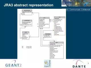
ILIAS - GWA N5 - Strega JRA3 General Meeting. Orsay - November 5th-6th, 2004. M1 Activities. Collaboration : 4 groups. Groups that have done some work during months 1 to 6 Virgo-Mat Group (INFN Firenze, Perugia, Pisa) CNRS, Laboratoire d’optique de l’ESPCI, Paris University of Glasgow, IGR

E N D
ILIAS - GWA N5 - Strega JRA3 General Meeting Orsay - November 5th-6th, 2004 M1 Activities
Collaboration : 4 groups • Groups that have done some work during months 1 to 6 • Virgo-Mat Group (INFN Firenze, Perugia, Pisa) • CNRS, Laboratoire d’optique de l’ESPCI, Paris • University of Glasgow, IGR • Groups that will produce deliverable before month 12 • Auriga LNL (The design of the capacitive readout for the Q-factor measurement has begun)
Aim of the M1 task • Aim: Investigation of mechanical thermal and optical properties of candidate materials for next generation detectors. • Materials considered: Si, CaF2, and white YAG.
Benefits for future detectors • Replacement of amorphous material by crystalline material for mirror substrates. • Decrease of the thermal noise contribution. • Increase of the Q-factor of mirror substrates. • Improvement of the optical performances (thermal lensing, birefringence,…)
M1 activities at Virgo-Mat laboratories • Advanced materials for mirror substrates • First year task: Room temperature measurement on Si and CaF2 • Michelson-Morley ITF in Perugia • Measurement of substrates for future ITF • Middle size CaF2 substrate • Mono-crystalline Si substrate “Virgo size” • Milestone and Deliverables • Cryogenic facilities for mechanical measurements fully operational • Involved groups • INFN Firenze • INFN Perugia • INFN Pisa
Mirror thermal noise • Bulk dissipation • thermodynamical dissipation in the bulk • new materials under investigation: CaF2, Silicon (Q meas. PG); • finite elements model of the mirror suspension in progress (Fi-Urb PG)
Calcium Fluoride • High thermal conductivity at low T, low expansion coefficient at low T • Disk of 180mm diameter, 38 mm thickness • Polished faces, rough lateral surface (to be polished) 107 • Measure dominated by excess losses • In any case comparable with FS in the same condition (not usable at low T)
Silicon test masses • Mono-Crystalline silicon disk • 350 mm diameter • 100 mm tick • Rough lateral surface • To be polished 107 • Excess losses under investigation and reduction
The cryogenic facility • Located in Perugia • Chamber for small samples • Under cooling in these days The clamping system
Evolution • No delay expected in the next year
M1 activities - Glasgow Group S. Reid1, G. Cagnoli1, D.R.M. Crooks1, E. Elliffe1, M.M. Fejer2, A. Heptonstall1, J. Hough1, P. Murray1, O. Solgaard2, S. Rowan1, R. Route2, P. Sneddon1, S. Zappe2 1 University of Glasgow 2 Stanford University
M1 activities at Glasgow • Aim to investigate: • internal dissipation of doped/un-doped bulk silicon as a function of temperature • dissipation due to aspects of test mass design related to use as diffractive optics • Milestone and Deliverables • Q measurement facility fully operational • Room temperature mechanical measurements on Si achieved • Low temperature Q measurement facility
Studies of silicon as a test mass substrate Clamp Suspension thread/wire • Preliminary room T measurements made of mechanical dissipation of bulk silicon samples suspended on silk thread or wire loops • Internal resonant modes of the samples excited; decay of mode amplitude measured Test mass To high voltage Excitation plate (behind mass) Schematic diagram of front view of suspended test mass. • Dissipation of two silicon samples of identical geometry, supplied by Stanford, was measured over a range of frequencies. Silicon samples cut along different crystal axes, [111] and [100]. The [111] sample was boron-doped.
Results for silicon at room temperature Sample [b] typically showed lower dissipation Sample [a]: [100] cut, nominally undoped Sample [b]: [111] cut, boron doped Reason for difference seen in measured loss factors (eg crystalline orientation of the sample, the dopant, or some other reason) is– under investigation – some evidence to suggest may be due to crystalline orientation Measured loss factors for two samples of bulk silicon • Lowest loss obtained so far = (9.6 +/- 0.3) x 10-9 • Comparable with the lowest loss factors measured at room temperature • Recall, varying dopant concentrations can vary the thermal conductivity of silicon. • This can impact both levels of thermoelastic dissipation and mirror figure distortion under thermal loads – requires further study.
M1 activities at ESPCI • Advanced materials for mirror substrates • First year task: Room temperature measurement on Si, CaF2, and YAG • Absorption measurements • Birefringence measurements • Milestone and Deliverables • Cryogenic facility for absorption measurements has begun (tested at 77K)
Room temp. absorption measurements • Measurements performed on an existing bench for CaF2 and YAG, bench built for Si. • CaF2 (@1064nm) • Between 2 and 10 ppm/cm, sample dependant, position dependant • White YAG (@1064nm) • ~10 ppm/cm • Si (@1300nm) • Undopped • N-doped high resisitivity <10 ppm/cm • P-doped high resistivity <10 ppm/cm Bench sensitivity limit, problem solved thanks to EGO (month 10 ?)
Si birefringence measurements • Silicon intrinsic birefringence • Tests on <111> (done month 6) and <100> samples • Theoretical investigation has begun (month 4) • Local (non-imaging bench) has been built (month 5) for orientation dependant birefringence measurements • Silicon induced birefringence • Imaging bench realization has begun (expected working month 9) for strain and dislocation induced birefringence.
Si intrinsic birefringence nmax=410-6 @1300nm
CaF2 and YAG birefringence measurements • Intrinsic and induced birefringence • Local (non-imaging bench) has been built (month 5) for orientation dependant birefringence measurements • Imaging bench operational. • Not tested on large scale single crystals
Evolution • No delay expected in the next year