Download
1 / 41
410 likes | 526 Views
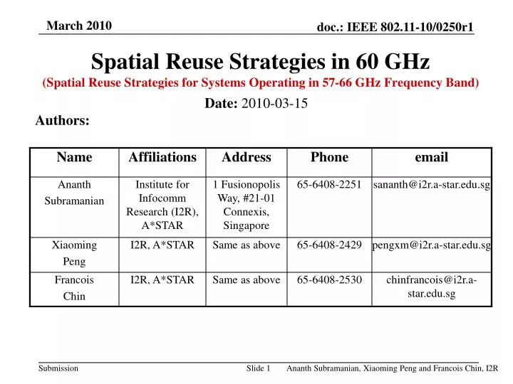
Spatial Reuse Strategies in 60 GHz (Spatial Reuse Strategies for Systems Operating in 57-66 GHz Frequency Band). Authors:. Date: 2010-03-15. Outline. Introduction - spatial reuse and device discovery Summary of our solution Details of our solution Information element (IE) proposed

E N D
Spatial Reuse Strategies in 60 GHz (Spatial Reuse Strategies for Systems Operating in 57-66 GHz Frequency Band) Authors: Date: 2010-03-15
Outline • Introduction - spatial reuse and device discovery • Summary of our solution • Details of our solution • Information element (IE) proposed • Caches proposed (extensions to NAV of IEEE 802.11-2007) • Device discovery strategies • Spatial reuse strategies • Rules / Addendum / Details 2
4 2 1 1 D B 3 3 4 2 4 1 E 3 2 1 2 C 4 3 4 1 G 1 4 3 2 F 2 3 4 1 A 3 2 Spatial Reuse and Device Discovery A device discovery strategy must allow a device to discover the orientation of each of its neighbors with respect to itself. Spatial reuse strategy must allow two or more pairs of devices within the Omni-directional transmission range of each other to communicate simultaneously.
Proposed spatial reuse strategies Proposed device discovery strategies IEEE 802.11-2007 MAC Summary of Our Solution • We propose spatial reuse strategy and device discovery schemes that • work with both sector antennas and phased array antennas, • work with DCF based medium access, PCF based medium access and HCF based medium access, • are backward compatible additions to IEEE 802.11-2007, • do not require location information. • We propose spatial reuse and device discovery strategies based on • Topology Information Element (IE) • Topology Matrix (TM) • Directional Network Allocation Vectors (DNAVs)
4 2 1 1 B D 3 3 2 4 4 1 E 3 2 1 2 C 4 3 4 1 G 1 4 3 2 F 2 3 4 1 A 3 2 Spatial Reuse and Device Discovery Every node (device, STA) is supposed to label its logical sectors consecutively in clockwise or anti-clock wise direction. (At a few places, we will explain the concept assuming that each STA has 4 sectors just for the sake of brevity) We propose that every STA (device) transmit Topology IEs, have DNAVs and a TM. We propose that STAs perform frequent device discovery phases to keep themselves updated of their respective neighborhood orientations (not necessarily locations). Figure : Network of STAs
Topology IE Format of the Topology IE An example format of the Topology IE STA Address fields are the addresses of the neighbors of STA that is transmitting the element. The Topology Information Bitmap field consists of N (=K) octets of 8-bit elements to indicate the logical sector usage (that is the logical sector used by a neighbor to communicate with the STA), where N is the total number of addresses included. The least six significant bits of an element ‘n’ indicate the number of the logical sector which can be any of zero (or 1) to sixty three (or 64) used by the neighbor ‘n’ to communicate with the STA. The most significant bit and the second most significant bit, both of an element ‘n’ may signify how many sectors on both sides of the logical sector given by the six least significant bits of the corresponding element are used for communication by the neighbor ‘n’ to communicate with the STA.
Topology IE We propose that the maximum number of sectors for a STA be 64 or 32 or 16. The above does not put any limitation on the number of beams a STA may have or steer. We also propose that if a STA has several neighbours, it may accommodate their STA addresses in multiple Topology IEs. A STA may be able to dynamically change the number of logical sectors it has but not more than once in every 32 x aMaxDiscoveryLatency TUs. aMaxDiscoveryLatency is a parameter that is proposed to be introduced. Possible values for this parameter are 64 or 128. Topology IEs are transmitted by a STA using discovery data blocks (details are in the following).
Topology IE Optionally, every device (STA; even PC or HC) shall generate a unique 16 bit address (Dev. Addr.). Topology IE transmitted by a device may have an additional field called the Transmitting Dev. Addr. field which is the unique 16 bit address generated by the transmitting device (device transmitting the Topology IE) for itself. In this case then, each of the STA Address fields in a Topology IE would be of two octets length instead of 6 octets if the generated addresses are used. Conflicts between 16 bit Dev. Addrs. are discovered using Topology IEs. If a device discovers that its Dev. Addr. is in conflict, it shall generate a new Dev. Addr. applicable from the end of transmission of its next discovery data block (see details that follow). Optionally, a Topology Control frame may be used to achieve the same functionality of Topology IE using rules given herein.
4 2 1 1 D B 3 3 4 2 4 1 E 3 2 1 2 C 4 3 4 1 G 1 4 3 2 F 2 3 4 1 A 3 2 Topology Matrix (TM) Figure : Example of TM at device ‘B’ TM is maintained by each device pertaining to itself and its neighbors as to which logical sector the device or its neighbour will use to communicate as a source with another device. Each row corresponds to a particular link (between STAs) in the network. Each row contains link information in regards to first STA address of the corresponding link, second STA address of the corresponding link, first STA address’s best logical sector(s) for that link and second STA address’s best logical sector(s) for that link.
Topology Matrix (TM) Each of the eight columns in the “STA Address 1’s Logical Sector(s)” tab or “STA Address 2’s Logical Sector(s)” tab in the TM corresponds to a bit. The least six significant bits of STA Address 1’s Logical Sector(s) tab indicate the number of the logical sector which can be any of zero (or 1) to sixty three (or 64) used by STA Address 1 to communicate with STA Address 2. The least six significant bits of STA Address 2’s Logical Sector(s) tab indicate the number of the logical sector which can be any of zero (or 1) to sixty three (or 64) used by STA Address 2 to communicate with STA Address 1. The most significant bit and the second most significant bit, both of either “STA Address 1’s Logical Sector(s)” tab or “STA Address 2’s Logical Sector(s)” tab together (as two bits) may signify how many sectors on both sides of the logical sector mentioned by the six least significant bits of the corresponding tab are used for communication by STA address 1 or STA address 2 respectively. In this case then, a STA may use up to 7 logical sectors to communicate with another STA.
Topology Matrix (TM) Optionally the two most significant bits of either “STA Address 1’s Logical Sector(s)” tab or “STA Address 2’s Logical Sector(s)” tab may inform how many sectors on one apriori known side of the logical sector given by the six least significant bits of the corresponding tab are used. This format of the TM is also proposed to be updated frequently by the STA based on device discovery results and Topology IEs received. The TM of a device may contain device addresses of devices that are up to two hops from the device. Information from other STAs about other links (where the STA is not a vertex) that is needed to update the format of the TM is received through the Topology IEs discussed earlier.
Directional Network Allocation Vectors (DNAVs) A STA that transmits or receives frames shall maintain one Directional Network Allocation Vector (DNAV) for each of its logical sectors that contains the remaining time that the logical sector shall not be used for transmission or reception because of a neighbour STA’s transmission or reception. Rules for using a DNAV are similar to those for NAV but that DNAV applies only to medium accessible by a particular sector.
Frames Proposed -Device Discovery Request frame Device-Discovery-Request frame The DA of the Device-Discovery-Request frame is the address of the STA which is the intended destination of the frame. The SA is the address of the STA transmitting the Device-Discovery-Request frame. The duration value is the time in microseconds required to transmit the pending frames (fragments) of the discovery data block (see details that follow). The Frame Control field of the above frame is as given in IEEE 802.11-2007 (Frame type for this frame is proposed to be ‘00’ and frame subtype is proposed to be ‘0110’).
Frames Proposed -Device Discovery Response frame Device-Discovery-Response frame The DA of the Device-Discovery-Response frame is the address of the STA which is the intended destination of the frame. The SA is the address of the STA transmitting the Device-Discovery-Response frame. The duration value is the time in microseconds required to transmit the pending frames (fragments) of the discovery data block. Frame type is proposed to be ‘00’ and frame subtype is proposed to be ‘0111’). Optionally the Device-Discovery-Request and Device-Discovery-Response frames can be control frames using the reserved sub-types. The frame bodies of the Device-Discovery-Request and Device-Discovery-Response frames shall contain the Topology Information Element.
Frames Proposed -CTS (Spatial Reuse) This frame uses a reserved subtype Frames Proposed -CF-Poll Response (This frame is needed if the PC incorporates only PCF and is not a HC with HCF implemented in it in entirety.) The duration value is the time in microseconds required to transmit the pending frames (fragments) or remaining time duration of TXOP. The Frame Control field of the CF-Poll-Response frame is as given in IEEE 802.11-2007 (Frame type for this frame is proposed to be ‘01’ and frame subtype is proposed to be ‘0111’). Optionally, the CF-Poll-Response frame may be a data frame.
Device Discovery Strategy (Mandatory Step) Back off slots O D1 D2 D3 D4 Medium Busy DIFS Discovery data block Medium idle Management/Control/data: O -- Omni-directional D1,D2, D3, D4 -- Directional Frame ‘O’ is Device Discovery Request frame in the discovery data block Inter Frame Spacing Back off slot Every STA transmits a discovery data-block using contention access of the medium. However, the STA that intends to transmit a discovery data-block has to ensure that the medium is available Omni-directionally based on its TM and its DNAVs. The above illustration is for DCF. But discovery data block can also be transmitted using CFP or HCCA when HC gives opportunity using QoS-CF-Poll frame. Note that the order of transmission of the directional frames is from sector 1 of that STA going sequentially up to the last sector of that STA.
4 1 B 3 2 4 1 E 1 3 2 2 D 4 1 2 3 C 4 3 4 1 G 1 4 3 2 F 2 3 4 1 A 3 2 Device Discovery Strategy (Mandatory Step) Assume ‘C’ is involved in transmission of discovery data block. Device ‘F’ with the knowledge of the frame end of the Omni-directional frame from ‘C’ and with the reception of 3rd directional frame from ‘C’ can know that STA ‘C’ would use ‘C’s sector ‘3’ to communicate with it. Note that in the above, every STA in the neighborhood of ‘C’ would be able to determine at the end of ‘C’s transmission of the discovery data block, which of ‘C’s sector would ‘C’ use to communicate with it. When STA ‘F’ sends a similar discovery data block, STA ‘C’ can infer in a similar manner that STA ‘F’ would use sector 1 to communicate with ‘C’ and update its TM. With the reception of Topology IEs from ‘C’ and ‘F’, all STAs including ‘C’ and ‘F’ can update their TMs.
Device Discovery Strategy (Optional Step) Back off slots O D1 D2 D3 D4 D’1 D’2 D’3 D’4 O’ Medium Busy DIFS Medium Idle Management/Control/data: O,O’ -- Omni-directional D1,D2,D3,D4 – Directional D’1, D’2,D’3,D’4 -- Directional Inter Frame Spacing Back off slot The STA that intends to initiate the discovery data-block transmission has to ensure that the medium is available Omni-directionally based on its TM and DNAVs. Frame O and O’ in the above are Device Discovery Request and Response frames respectively. The above illustration is for DCF. But discovery data block can also be transmitted using CFP or HCCA when HC gives opportunity using QoS-CF-Poll frame. Note that the order of transmission of the directional frames from a STA is from sector 1 of that STA going sequentially up to the last sector of that STA.
A Few Rules Concerning Device Discovery and Spatial Reuse A STA is said to have established orientation (device discovery) information with a neighbor if the STA has obtained information about the STA’s best logical sector(s) to communicate with the neighbor and the neighbor’s best logical sector(s) to communicate with the STA. Toward this, the STA should have transmitted a Topology IE with the neighbor’s address included in it and should have also received a Topology IE from the neighbor with it’s address included in the neighbor’s Topology IE.
Spatial Reuse Transmission of RTS frames : Before any RTS packet is sent, the STA shall determine if it had obtained a TXOP in the logical sector it intends to send the directional data. If the STA had obtained a TXOP for Omni-directional transmission, the STA shall send the RTS packet Omni-directionally (if RTS is sent). Concerning transmission of RTS - only if the STA has the medium unavailable for Omni-directional transmission, should the STA send a directional RTS (using all available sectors) should it decide to send a RTS. The upper bound on the duration field in the RTS packet that is sent Omni-directionally is aTXOPLimit (a parameter). The upper bound on the duration field in the RTS packet that is sent directionally is the value of the least of the STA’s non-zero DNAVs for its logical sectors minus RTS frame transmission time.
Spatial Reuse Transmission of CTS frames : If the medium is idle and available in all of its logical sectors, the STA shall send the CTS packet Omni-directionally with duration field derived from the duration field in the received RTS packet. If the medium is not idle in all the logical sectors but available in the logical sector it intends to receive the directional data, the STA shall send the CTS packet directionally in the logical sector it intends to receive directional data (and also in the other available sectors). • In the CTS packet sent directionally by the STA, the upper bound on the • duration field in the CTS packet shall be the minimum of - • the least of the STA’s non-zero DNAVs for its logical sectors minus CTS • frame transmission time. • the duration field (for Omni-directional CTS) as derived from the RTS packet • received by the STA.
Spatial Reuse Concerning sending a directional RTS frame or directional CTS frame or directional initiating frame of a TXOP, the device shall send the frame simultaneously in every logical sector whose DNAV has a zero value and whose medium has been available for more than DIFS/AIFS[AC] while sending the frame in the logical sector it intends to transmit or receive data. This can easily be done using sector antennas or through beamforming with phased array antennas. A device shall not transmit a directional RTS frame (or initial frame at the start of a TXOP) in a logical sector if the DNAV of any of the other logical sectors is zero and the medium in that other logical sector whose DNAV is zero has been idle for less than SIFS/DIFS. If a device has a sector (numbered S) with non zero DNAV, the device shall not send a CTS frame in a sector that is diametrically and geometrically opposite to that sector S (for the purpose of receiving data in the sector geometrically opposite S). All control frames transmitted directionally should be with power control to offset the directional transmit antenna gain.
4 2 1 1 D B 3 3 4 2 4 1 E 3 2 1 2 C 4 3 4 1 G 1 4 3 2 F 2 3 4 1 A 3 2 Spatial Reuse Using EDCA As an example, if STA ‘A’ sends an Omni-directional RTS to STA ‘C’, then upon reception of the above RTS, all the neighbors of ‘A’ shall infer from the RTS received that the intended destination is STA ‘C’. Each of the neighbors of ‘A’ shall also after looking at its TM set it’s DNAVs after inferring that ‘A’ intends to use its logical sector 1 to communicate with STA ‘C’s logical sector 4. Device ‘G’ sets its DNAV for sector 1 as sector 4 of STA ‘C’ is reachable from its sector 1. Device ‘F’ sets the DNAV for its logical sector 2 using the duration field from received RTS packet, STA ‘D’ sets the DNAV for its logical sector 3, and STA ‘B’ sets the DNAV for its logical sector 3.
2 4 1 1 D B 3 3 2 4 4 1 E 3 2 1 2 C 4 3 4 1 G 1 4 3 2 F 2 3 4 1 A 3 2 Spatial Reuse Using EDCA Upon reception of the RTS from ‘A’, STA ‘C’ infers from its TM that it has to use its logical sector 4 for receiving packets from ‘A’ and assuming its DNAV for sector 4 is zero along with all of its other DNAVs (with Omni-directional medium availability), the STA ‘C’ shall respond with a CTS packet with duration derived from duration from RTS. Device ‘C’ shall also send Omni-directional CTS since the DNAVs of all its sectors were zero with medium availability (just prior to transmission of CTS). Upon reception of a CTS from STA ‘C’, each of STAs ‘G’, ‘F’, ‘B’, ‘E’ and ‘D’ with the use of its own TM needs to update its DNAVs.
4 2 1 1 D B 3 3 4 2 4 1 E 3 2 1 2 C 4 3 4 1 G 1 4 3 2 F 2 3 4 1 A 3 2 Spatial Reuse Using EDCA Now if STA ‘B’ wants to send a RTS packet to ‘D’ when ‘A’ and ‘C’ communicate, we suppose it infers that its DNAV for sector 3 alone is non zero with medium availability in other sectors. Hence should it choose to send a RTS, it should send RTS directionally to ‘D’ using sector 2 (as well as sectors 1 and 4; beam pattern such as null in sector 3). Since ‘D’ has a non-zero DNAV for its sector 3 alone (because of link ‘A’-‘C’), ‘D’ shall send a CTS directionally to ‘B’ using sectors 1 and 2 and 4 (assuming medium availability) with duration field set to a value less than or equal to the DNAV of its sector 3 minus CTS frame transmission time.
Spatial Reuse Using EDCA A STA shall not send any RTS or CTS frame or any other frame other than Device Discovery Request frame if it had not sent even one discovery data block in past aMaxDiscoveryLatency Time Units (TUs). A STA shall not send a RTS or CTS or any initiating frame to a neighbor with which it had not established orientation (device-discovery) information even once in the past 2 x aMaxDiscoveryLatency TUs. If a STA receives an Omni-directional RTS or CTS or initiating frame not addressed to itself from a neighbor or to a neighbor with which it had not established orientation (device-discovery) information in the past 2 x aMaxDiscoveryLatency TUs, the STA shall update all its DNAVs of its logical sectors using the duration mentioned in the received such frame.
Spatial Reuse Using EDCA If a STA receives a directional or Omni-directional RTS addressed to itself from a neighbor with which it had not established orientation (device-discovery) information even once in the past 2 x aMaxDiscoveryLatency TUs, it shall not respond with a CTS frame. A STA is allowed to send RTS or CTS or initiating frame to a neighbor only if the orientation (device-discovery) information had not changed in its TM concerning that neighbor (for all the links the neighbor is involved with as a vertex) for the past 4 x aMaxDiscoveryLatency TUs.
4 2 1 1 D B 3 3 2 4 Frame transaction of STA ‘A’ to ‘G’ frame/fragment: O,O’ -- Omni-directional D1, D2, D3, D4 – Directional D’1, D’2, D’3, D’4 – Directional F1, F2 – frames/fragments A1, A2 – ACK O’ D’1 D’2 D’3 D’4 F1 A1 F2 A2 SIFS 4 1 E Beacon of the HC (‘C’) O D1 D2 D3 D4 QoS CF-Poll frame of HC (‘C”) to ‘A’ 3 2 Frame transmissions of STA ‘B’ to ‘D’ Discovery data block of the HC (device ‘C’) 1 2 C 4 3 4 1 G 1 4 3 2 F 2 3 4 1 A 3 2 Spatial Reuse Using CFP - HCF After the reception of QoS CF-Poll frame from ‘C’, device ‘A’ may utilize the TXOP by sending a RTS or an initiating frame or a Device-Discovery-Request frame as the first frame. CFP
2 4 1 1 D B 3 3 2 4 4 1 E 3 2 1 2 C 4 3 4 1 G 1 4 3 2 F 2 3 4 1 A 3 2 Spatial Reuse Using CFP - HCF Optionally device ‘A’ may send a QoS CF-Poll Response frame (format same as for CF-Poll response frame except with the addition of QoS control field) in response to a received QoS CF-Poll frame. Device ‘B’ will also be able to initiate frame transactions to ‘D’ after consulting with its TM and DNAVs (if device A did not send a Device Discovery Request frame). However, the device ‘B’ shall ensure that frame transactions initiated by it to device ‘D’ shall complete before the duration of TXOP specified in the RTS or initiating frame from A elapses. Optionally, device ‘B’ shall send a RTS frame as the first of its frame transactions and device ‘D’ shall respond with a CTS frame (subject to rules given above). The above would allow other pairs of devices to use the medium as well using spatial reuse strategies.
Frame transmissions of device ‘A’ to ‘G’ frame/fragment: O,O’ -- Omni-directional D1, D2, D3, D4 – Directional D’1, D’2, D’3, D’4 – Directional F1, F2 – frames/fragments A1, A2 – ACK O’ D’1 D’2 D’3 D’4 F1 A1 F2 A2 CF-Poll Response frame of ‘A’ (only if using PCF) SIFS Beacon of the PC (‘C’) O D1 D2 D3 D4 CF-Poll frame of PC ( ‘C’) to ‘A’ Frame transmissions of device ‘B’ to ‘D’ Discovery data block of the PC (device ‘C’) CFP Spatial Reuse Using CAP (HCCA) The spatial reuse strategies during CAP are similar to those given for CFP using HCF. Spatial Reuse Using CFP - PCF We propose that a device be allowed to send a sequence of frames/fragments during CFP. However, before a device (non PC) may send a fragment burst in a CFP, the device shall first send a CF-Poll-Response frame in response to a received CF-Poll frame.
4 2 1 1 D B 3 3 4 2 4 1 E 3 2 1 2 C 4 3 4 1 G 1 4 3 2 F 2 3 4 1 A 3 2 Spatial Reuse Using CFP - PCF After the reception of the frame O’ from ‘A’, device ‘B’ will be able to initiate frame transactions to ‘D’ after consulting with its TM and DNAVs. However, the device ‘B’ shall ensure that frame transactions initiated by it to device ‘D’ shall complete before the duration mentioned in the CF-Poll-Response frame from ‘A’ elapses. Optionally, device ‘B’ shall send a RTS frame as the first of its frame transactions and device ‘D’ shall respond with a CTS frame (subject to rules given above). The above would allow other pairs of devices to use the medium as well using spatial reuse strategies.
Medium Availability For CP purposes, a device shall consider the medium in a logical sector to be busy for any of the following conditions: — When its Clear Channel Assessment (CCA) mechanism indicates that the medium in this logical sector is busy (though the medium may be directionally available or idle in other logical sectors); — When the device’s DNAV for this logical sector is greater than zero; — When the device is transmitting or receiving a frame on the medium using this logical sector ; — When the Duration announced in a previously transmitted frame from or to a logical sector of a neighbor of the device that is reachable by this logical sector of the device (inferred using TM) has not yet expired; At all other times a device may consider the medium in a logical sector to be idle The medium is considered to be idle by the device Omni-directionally if the medium is idle for each of its logical sectors. The medium is considered by the device to be available in a logical sector if the medium in the logical sector is idle and the corresponding DNAV is zero.
Back-off Procedure and CCA A STA shall maintain a back off counter for every Access Category (AC) for Omni-directional transmission purposes. In addition to the above, we propose that a STA shall maintain an independent back off counter for every AC for every logical sector. The back off counter for an AC for a logical sector shall be decremented in a manner similar to that in IEEE 802.11-2007. A STA shall be able to independently perform Clear Channel Assessment in each of its logical sectors. A STA shall also be able to independently invoke a back off for the medium in any logical sector.
TXOP The device shall consider itself to have obtained a TXOP in a logical sector if it meets the following conditions: — The device has one or more newly arrived frames or newly generated frames; — The device had a backoff counter corresponding to that logical sector of zero value and had no frames prior to the arrival or generation of the new frames; — The device determines that the medium in that logical sector has been available for DIFS/AIFS[AC] or longer; The device shall also consider itself to have obtained a TXOP in a logical sector if it meets the following conditions: — The device has one or more frames buffered for transmission, including retry; — The device decremented its backoff counter corresponding to that logical sector from one to zero and no frame was transmitted by the device in that logical sector (with medium in that logical sector having remained available (for DIFS/AIFS[AC] or longer)) since then; Similar rules as above apply concerning Omni-directional TXOP and TXOPs for ACs.
A Few Rules Concerning Spatial Reuse and Frame Transmissions • A STA shall not initiate a frame transaction with a neighbour (using spatial reuse strategies) during the frame transmission period between another pair of STAs (from which it had received a RTS or a CTS or any initiating frame) unless - • its TM had been updated (confirmed) at least once in the past 2 x aMaxDiscoveryLatency TUs concerning the link between the other pair of STAs • it had established orientation (device discovery) information with both the STAs (each of them) of the other pair at least once in the past 2 x aMaxDiscoveryLatency TUs • the entries in its TM concerning all the links where any STA of the other pair is a vertex had not changed in the past 4 x aMaxDiscoveryLatency TUs . • Toward this, the STA should have received topology IEs from both the STAs of the other pair including each other’s address at-least once (from each of the STAs of the other pair) in the past 2 x aMaxDiscoveryLatency TUs.
A Few General Rules A device may not consider another device a neighbour if the device had not received any discovery data block in the past 4 x aMaxDiscoveryLatency TUs from the other device. Whether using DCF or HCF, a device may initiate frame transaction with a neighbor during the frame transmission period between another pair of devices (from which it had received a RTS or a CTS or a QoS-CF-Poll-Response frame or any initiating frame) if one of the devices in the other pair is not a neighbour of the device and if the logical sector proposed to be used by the neighbour of the device in the other pair is unreachable from the device (subject to its TM and DNAVs and the rule below). If a device receives a RTS or a CTS or any initiating frame destined to another device (recipient is another device) which is not the neighbor of the device, then the device shall update its DNAVs of its sectors that can reach the sender of the above frame and all the other DNAVs of its sectors that are in the one half of its transmission reachable area facing the sender of the above frame taking in to account the duration value included in the received above frame.
A Few General Rules The PC or HC shall send at least one CF-Poll frame or a QoS CF-Poll frame to a device every aMaxDiscoveryLatency TUs or ‘x’ DTIMs, where ‘x’ is a parameter. SIFS after the reception of the CF-Poll frame or a QoS CF-Poll frame, the device may transmit a Device-Discovery-Request frame and subsequently sequential directional frames as part of the discovery data block. A device may consider a sector as to be used to communicate with a neighbor if the signal strength received in that sector from the neighbor is above a certain threshold or/and above a certain fraction of the maximum signal strength in any of its sector(s) (direction) while receiving frames from that neighbor. Topology IE shall always be sent in every Device-Discovery-Request frame and every Device-Discovery-Response frame. The RA or DA of Device-Discovery-Request frame sent using mandatory step shall be a broadcast address. A device shall update its TM (immediately within SIFS) concerning all the links a neighbor is involved with after receiving a Topology IE from that neighbor. If a link (where the neighbor is a vertex) has been modified in the device’s TM or added to the device’s TM, the device shall not send any RTS or CTS or initiating frame to that neighbor in the next 4 x aMaxDiscoveryLatency TUs after the above SIFS.
Alternatives for Device Discovery Strategies A device replaces each of its directional frame it transmits pertaining to device discovery with an Omni-directional frame (in the mandatory and optional steps given for device discovery). In these alternatives, the recipient device after receiving the first Omni-directional frame from the sender in Omni-directional mode later tunes its direction of listening sequentially sector by sector during the times of subsequent Omni-directional frames’ transmissions by the sender. With the above alternatives, the Topology Information Bitmap field in a Topology IE shall have the same format but that the logical sector usage signified by an element ‘n’ in the Topology Information Bitmap field shall denote the logical sector of the device used by the device to communicate with a neighbour ‘n’.
Conclusion • We have proposed spatial reuse and device discovery strategies based on • Topology Information Element (IE) • Topology Matrix (TM) • Directional Network Allocation Vectors (DNAVs)
Straw Poll • Do you support inclusion of the technique, - Spatial Reuse and Device Discovery Strategies as described in 10/0250r1 in the TGad draft amendment? • Y: • N: • A: Slide 41