Download
1 / 62
620 likes | 626 Views
Learn the principles and practice of computer networking, with a focus on internet architecture and protocols. This introductory graduate course covers topics such as network edge, core, and access, protocol layers, and service models.

E N D
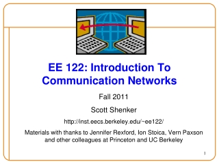
EE 565 PMPComputer-Communication Networks Payman Arabshahi Department of Electrical Engineering
Team Instructor: Payman Arabshahi, Dept. of Electrical Engineering and Applied Physics Laboratory, payman@ee.washington.edu, Tel: (206) 221-6990. Office hours: after class (EEB 045), or by appointment. Teaching Assistant: Michael Carosino, mcaros@uw.edu, (509) 521-3454, Office Hours: Sundays 3:00 - 5:00 pm, and Tuesdays 6:00 - 8:00 pm in Sieg 232, or by appointment.
Time Wednesdays06:00 – 09:50 pm (class - EEB 045)
Introductory graduate course in computer networking Learn principles of computer networking Learn practice of computer networking Internet architecture/protocols as case study by the time you are finished … Goals: Learn a lot (not just factoids, but principles and practice) Have fun! (learn how to spoof mail, sniff network traffic, write cool network apps, and more) What is this course about?
Introductory graduate course in computer networking Who is this course for? PMP students Prerequisites: Algorithms, operating systems, programming skills, probability and statistics Course Information • Course materials: • Text: Computer Networking: A Top Down Approach, J. Kurose & K. Ross, Addison Wesley, 7th ed., 2017. • Class notes
Class web site: http://courses.washington.edu/ee565/ Course Information the most important piece of info you will receive today! • everything is posted on this site! • syllabus • TA info • class notes (powerpoint, pdf) • assignments • nothing will be handed out in class :-)
Course Information • Class mailing list: ee565b_wi17@u.washington.edu • Grading: • All homeworks will be due in class, one week from assigned date. No late homeworks will be accepted. • There will be no make-up exams; absences with valid reasons will have credit pro-rated to the Final. • All exams are in-class, closed-book; two 8 1/2 x 11 sheets of formulas/notes allowed for Midterm and four sheets for the Final. Coursework approx amount approx % written homeworks 5 15% lab assignments (Wireshark) 5 15% Midterm 30% Final 40%
Odds and ends… me in-class style: interaction, questions (please!) incomplete policy academic honesty getting into this course… Software to use (Wireshark) questions, comments, … ??? Course Information
Course Overview Part 1: Introduction (1 class, text: Chapter 1) • what is the Internet, What is a protocol? • network edge, network core, network access • physical media • delay, loss in packet-switched networks • protocol layers, service models • Internet backbones, NAPs and ISPs • brief history of networking, Internet
A Top-Down Approach We’ll cover networking top-down • end-system applications • transport: TCP/UDP • network core: routing, hooking nets together • link-level protocols, e.g., Ethernet • other stuff: security, mobility, management,
Course Overview Part 2: Application Layer (2 classes, text: Ch. 2) • principles of application-layer protocols • World Wide Web: HTTP • file transfer: FTP • electronic mail in the Internet • the Internet's directory service: DNS • socket programming
Course Overview Part 3: Transport Layer (2 classes, text Ch. 3) • Transport-layer services and principles • Multiplexing and demultiplexing applications • Connectionless transport: UDP • Principles of reliable of data transfer • TCP case study • Principles of congestion control • TCP congestion control MIDTERM EXAM (approx)
Course Overview Part 4: Network Layer (2 classes, text: Ch. 4) • introduction and network service model • what’s inside a router? • routing principles (algorithms) • hierarchical routing • IP: the Internet Protocol • Internet routing: RIP, OSPF, BGP
Course Overview Part 5: Link Layer, LANs (1.5 classes, text: Ch. 5) • introduction, services • error detection, correction • multiple access protocols, LANs • LAN addresses, ARP • Ethernet • PPP: the Point-to-Point protocol • A network as a link layer: ATM, MPLS
Course Overview Part 6: Wireless and Mobile Networks (1 class, Ch. 6) • wireless link characteristics • the wireless link: • 802.11 • cellular Internet access • mobility principles • mobility in practice: • mobile IP • mobility in cellular networks
ISO/OSI Layered Communication Model • Layered communication models are traditionally used for data communication. • Layering is an example of a divide-and-conquer strategy: if the problem is too complicated, divide it into smaller and more manageable parts and solve each subproblem. Does not necessarily lead to the most efficient solution. • Each layer forms a model of the layers below and implement a service to the layer above. For instance, the physical layer deals with transmitting bits from one node to another. The data link layer sees a bit pipe, but not how the bit pipe is implemented with electronics, radio circuitry or optoelectronics. • Each layer also communicates with its counterpart on another node over the virtual link provided by the layers below it. • Each layer has a standard defined input and a standard defined output.
OSI Model Explained • We look at a top-down explanation of the OSI Model. • It starts with the user's PC and it follows what happens to the user's file as it passes though the different OSI Model layers. • We use this approach here to show how the user's files are transformed (through the layers) into a bit stream for transmission on the network. • The keyboard and application are shown as inputs to the CPU (requesting access to the hard disk). The keyboard requests accesses through user inquiries (such as “dir" or “ls” commands) and the application seeks access through "File Openings" and "Saves". The CPU, through the Disk Operating System, sends and receives data from the local hard disk ("C:"). Basic PC logical flowchart.
OSI Model Explained • The Network Redirector is a Terminate and Stay Resident program: it presents the network hard disk as another local hard disk ("G:") to the CPU. • All CPU requests are intercepted by the "Network Redirector". It checks to see if either a local or a network drive is requested. • If a local drive is requested, the request is passed on to the DOS. • However, if a network drive is requested, the request is then passed on to the network operating system (NOS). Simple network redirection.
OSI Model Explained • Email, client-server databases, games played over the network, print and file servers, remote logons, and network management programs (or any "network aware" applications) are all aware of the network redirector. • They have the ability to communicate directly with other "network applications" on the network. • The "Network Aware Applications" and the "Network Redirector" make up Layer 7 – the Application layer of the OSI Model. PC Workstation with network aware software.
OSI Model Explained • The Network Redirector sends CPU operating system native code to the network operating system. • But the coding and format of the data is not recognizable by the network operating system. • The data consists of file transfers and network calls by network aware programs. • For example, when a dumb terminal is used as a workstation (in a mainframe or minicomputer network), the network data is translated into (and from) the format that the terminal can use. • Layer 6 – the Presentation layer presents data to and from the terminal using special control characters to control the screen display (LF-line feed, CR-carriage return, cursor movement, etc..). The presentation of data on the screen would depend on the type of terminal that's used: VT100 …
OSI Model Explained • The Presentation layer also strips the pertinent file from the workstation operating system's file envelope. The control characters, screen formatting, and workstation operating system envelope are all stripped or added to the file (if the workstation is receiving or transmitting data to the network). • The Presentation Layer also controls security at the file level: this provides both file locking and user security. • At this point, the data is contiguous and complete (i.e. one large data file). Presentation layer.
OSI Model Explained • The Presentation layer relieves the Application layer of concern regarding syntactical differences in data representation within the end-user systems. • MIME encoding, encryption and similar manipulation of the presentation of data is done at this layer. • An example of a presentation service would be the conversion of a EBCDIC-coded text file to an ASCII-coded file.
OSI Model Explained • Layer 5 – the Session layer manages the communications between the workstation and the network. • It directs the information to the correct destination, and identifies the source to the destination. • It identifies the type of information as data or control. • It manages the initial start-up of a session, and the orderly closing of a session. • The Session layer also manages Log on procedures and Password recognition. Session layer.
OSI Model Explained • The Session layer provides the mechanism for managing the dialogue between end-user application processes. • It provides for either duplex or half-duplex operation and establishes checkpointing, adjournment, termination, and restart procedures. • This layer is responsible for setting up and tearing down TCP/IP sessions.
OSI Model Explained • In order for the data to be sent across the network, the file must be broken up into usable small data segments (typically 512 - 18K bytes). • Layer 4 – the Transport layer breaks up the file into segments for transport to the network, and combines incoming segments into a contiguous file. • The Transport layer does this logically, not physically, and it is done in software as opposed to hardware. • The Transport layer provides error checking at the segment level (frame control sequence). This makes sure that the datagrams are in the correct order: the Transport layer will correct out of order datagrams. • The Transport layer guarantees an error-free host to host connection. It is not concerned with the path between machines. Transport layer.
OSI Model Explained • The purpose of the Transport layer is to provide transparent transfer of data between end users, thus relieving the upper layers from any concern with providing reliable and cost-effective data transfer. • The transport layer controls the reliability of a given link. • Some protocols are stateful and connection oriented. This means that the session layer can keep track of the packets and retransmit those that fail. • The best known example of a layer 4 protocol is TCP.
OSI Model Explained • Layer 3 – the Network layer is concerned with the path through the network. • It is responsible for routing, switching, and controlling the flow of information between hosts. • The Network layer converts the segments into smaller datagrams than the network can handle: network hardware source and destination addresses are also added. • The Network layer does not guarantee that the datagram will reach its destination. Network layer.
OSI Model Explained • The Network layer provides the functional and procedural means of transferring variable length data sequences from a source to a destination via one or more networks while maintaining the quality of service requested by the Transport layer. • The Network layer performs network routing, flow control, segmentation/de-segmentation, and error control functions. • The router operates at this layer – sending data throughout the extended network and making the Internet possible, although there are layer 3 (or IP) switches.
OSI Model Explained • Layer 2 – the Data Link layer is a firmware layer of the network interface card. • It puts the datagrams into packets (frames of bits: 1s & 0s) for transmission, and assembles received packets into datagrams. • It works at the bit level, and adds start / stop flags and bit error checking (CRC or parity) to the packet frame. • Error checking is at the bit level only: packets with errors are discarded and a request for re-transmission is sent out. • The Data Link layer is primarily concerned with bit sequence. Data Link layer.
OSI Model Explained • The Data Link layer provides the functional and procedural means to transfer data between network entities and to detect and possibly correct errors that may occur in the Physical layer. • The addressing scheme is physical which means that the addresses are hard-coded into the network cards at the time of manufacture. • The best known example of this is Ethernet. • Other examples of data link protocols are HDLC and ADCCP for point-to-point or packet-switched networks and LLC and Aloha for local area networks. • This is the layer at which bridges and switches operate. • Connectivity is provided only among locally attached network nodes.
OSI Model Explained • Layer 1 – the Physical layer concerns itself with the transmission of bits. • It also manages the network card's hardware interface to the network. • The hardware interface involves the type of cabling (coax, twisted pair, etc.), frequency of operation (1 Mbps, 10Mbps, etc.), voltage levels, cable terminations, topography (star, bus, ring, etc.), etc. • Examples of Physical layer protocols are as follows: 10Base5 - Thicknet, 10Base2 - Thinnet, 10BaseT - twisted pair, ArcNet, FDDI, etc. Physical layer.
OSI Model Explained • The physical layer defines all electrical and physical specifications for devices. • This includes the layout of pins, voltages, and cable specifications. • Hubs and repeaters are physical-layer devices. • The major functions and services performed by the physical layer are: • Establishment and termination of a connection to a communications medium. • Participation in the process whereby the communication resources are effectively shared among multiple users. For example, contention resolution and flow control. • Modulation, or conversion between the representation of digital data in user equipment and the corresponding signals transmitted over a communications channel. This is signals operating over the physical cabling - copper and fiber optic, for example. SCSI operates at this level.
OSI Model Explained • Layer-Specific Communication • Each layer may add a Header and a Trailer to its Data (which consists of the next higher layer's Header, Trailer and Data as it moves through the layers). • The Headers contain information that specifically addresses layer-to-layer communication. • For example, the Transport Header (TH) contains information that only the Transport layer sees. All other layers below the Transport layer pass the Transport Header as part of their Data.
OSI Model Explained Layer-specific communication.
OSI Model Explained OSI Model Functional Drawing.
OSI Model Explained • The mnemonics "People Design Networks To Send Packets Accurately", "Please Do Not Throw Sausage Pizza Away", and "All People Seem To Need Data Processing" may help you remember the layers. • Real-world protocol suites often do not strictly match the seven-layer model. • There can be some argument as to where the distinctions between layers are drawn; there is no one correct answer. • However, most protocol suites share the concept of three general sections: media, covering layers 1 and 2; transport, covering layers 3 and 4, and application, covering layers 5 through 7. • Strict conformance to the OSI model has not been a common goal in real-world networks, partly due to the negative view of the OSI protocol suite.
OSI Model Explained • Andrew Tanenbaum argues in his popular textbook Computer Networks that the failure of the OSI suite to become popular was due to • Bad timing – the model was finished only after a significant amount of research time and money had been spent on the TCP/IP model. • Bad technology, because the session and presentation layers are nearly empty, whereas the data link layer is overfull. • Bad implementations, since early ones were notoriously buggy and in the early days, OSI became synonymous with poor quality, whereas early implementations of TCP/IP were more reliable. • Bad politics, because TCP/IP was closely associated with Unix, making it popular in academia, whereas OSI did not have this association. • However the model is still the general reference standard for nearly all networking documentation. All networking phrases referring to numbered layers, such as "layer 3 switching", refer to this OSI model.
OSI Model Explained • The 7 layer model has often been extended in a humorous manner, to refer to non-technical issues or problems. A common joke is the 9 layer model, with layers 8 and 9 being the "financial" and "political" layers. • Network technicians will sometimes refer euphemistically to "layer-eight problems," meaning problems with an end user and not with the network. • Carl Malamud, in his book Stacks, defines layers 8, 9, and 10 as "Money", "Politics", and "Religion". The "Religion layer" is used to describe non-rational behavior and/or decision-making that cannot be accounted for within the lower nine levels. (For example, a manager who insists on migrating all systems to a Microsoft platform "because everyone else is doing it" is said to be operating in Layer 10.) • The OSI model has also sometimes been jokingly called the "Taco Bell model", since the restaurant chain has sometimes sold a 7 layer burrito.
James Bond Meets the 7 Layer OSI Model • James Bond meets Number One on the 7th floor of the spy headquarters building. Number One gives Bond a secret message that must get through to the US Embassy across town. • Bond proceeds to the 6th floor where the message is translated into an intermediary language, encrypted and miniaturized. • Bond takes the elevator to the 5th floor where Security checks the message to be sure it is all there and puts some checkpoints in the message so his counterpart at the US end can be sure he’s got the whole message. • On the 4th floor, the message is analyzed to see if it can be combined with some other small messages that need to go to the US end. Also if the message was very large it might be broken into several small packages so other spies can take it and have it reassembled on the other end.
James Bond Meets the 7 Layer OSI Model • The 3rd floor personnel check the address on the message and determine who the addressee is and advising Bond of the fastest route to the Embassy. • On the 2nd floor the message is put into a special courier pouch (packet). It contains the message, the sender and destination ID. It also warns the recipient if other pieces are still coming. • Bond proceeds to the 1st floor where Q has prepared the Aston Martin for the trip to the Embassy. • Bond departs for the US Embassy with the secret packet in hand. On the other end the process is reversed. Bond proceeds from floor to floor where the message is decoded. • The US Ambassador is very grateful the message got through safely. http://www.lewistech.com/rlewis/Resources/james.aspx
The Shannon Model Claude Elwood Shannon - 17 April 1961 (photograph by Göran Einarsson)
The Shannon Model Basic elements of a digital communication system Claude Shannon, 1916-2001. His famous paper, “A Mathematical Theory of Communication”, was written in 1948.
The Shannon Model Basic elements of a digital communication system: Information rate: Rb=1/Tb Energy per bit: Eb = PTb Transmitter/Receiver pair.
The Shannon Model • The task of the receiver blocks is basically to undo the transmitter blocks. • The demodulator decides which bits where most likely transmitted by the transmitter. • The channel decoder inspects the received bits to detect and correct errors. • The source decoder formats the bit stream into a form suited to the sink. • Inevitably, there will be errors in this process due to channel noise and distortion. • The main performance measure is the bit error rate: the probability that a received bit is not equal to the transmitted bit. • It is the task of the channel encoder/decoder and modulator/demodulator to reduce the bit error probability to a level which is acceptable for the source decoder and sink. Example: GSM bit error rate after demodulation is 0.1-0.01, after channel decoding < 0.001 (acceptable for speech communication; much lower error rates usually required by data services).
The Shannon Model • In the Shannon model of a one-way digital communication link information from the source is to be transmitted to the sink. • The transmitter and receiver consist of three blocks each. • The source emits bits at a certain rate Rs bits/s; the source encoder reduces this bit rate by removing redundancy and unimportant information from the source bit stream. Example: GSM Rs = 64 kbps output rate 13 kbps. • The channel encoder introduces parity bits (or redundancy) to enable the receiver to detect and possibly correct errors that occur on the channel. Example: GSM channel encoder adds approximately one parity bit per information bit: output rate approximately 26 kbps. • The modulator transforms the coded bits into waveforms suitable for the channel. Example: GSM bits are (roughly) represented with sine waves of different frequencies: one frequency for a 0 bit and a different one for a 1 bit. • The channel typically distorts the transmitted signal and adds noise.
Finally • What design principles to use? • J.H. Saltzer, D.P. Reed, and D.D. Clark, "End-To-End arguments in system design", ACM Transactions on Computer Systems, vol. 2, no. 4, Nov. 1984. • B. Carpenter, RFC 1958, Architectural Principles of the Internet, 1996. • D. Thaler and B. Aboba, RFC 5218, What Makes for a Successful Protocol? 2008.
Advice for building product, networks, … life! Andrew Tanenbaum’s and David Wetherall’s adaption of RFC 1958, in their classic text, Computer Networks. This synopsis can be taken in a more general sense and applied to building successful products and even contains some life lessons