Download
1 / 64
660 likes | 1.04k Views
Chapter 9 Ethernet – Part 2. Generic Data Link Frame Format. Preamble or Start Field When computers are connected to a physical medium, there must be a way they can grab the attention of other computers to broadcast the message, "Here comes a frame!"

E N D
Generic Data Link Frame Format Preamble or Start Field • When computers are connected to a physical medium, there must be a way they can grab the attention of other computers to broadcast the message, "Here comes a frame!" • Various technologies have different ways of doing this process, but all frames, regardless of technology, have a beginning signaling sequence of bytes. • Depending up frame format: Preamble = 7 bytes, Start or Start of Frame Delimiter (SFD) = 1 byte
Generic Data Link Frame Format Address Field • We saw how IEEE 802.3 uses Destination and Source Addresses. • By the way: Any idea how a serial data link frame is addressed? • Ethernet: • Unicast address – MAC address of a single device • Broadcast address – All devices (All 1 bits, All F’s in Hex) • Multicast address – Specific group of devices
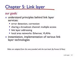
Unicast, Multicast, Broadcast Destination Addresses • Unicast address: A single Ethernet frame to be received by a single station. • Unknown Unicast: This is from the perspective of a switch, when the unicast address is not in its MAC Address Table • Multicast address: A single Ethernet frame to be received by a group of stations. • Broadcast address: Special case of a multicast address, which is all 1’s. This is an Ethernet frame to be received by all stations.
Generic Data Link Frame Format Type Field • Usually information indicating the layer 3 protocols in the data field, I.e. IP Packet. • Type field values of particular note for IEEE 802.3 frames include: • 0x0600 XNS (Xerox) • 0x0800 IP (Internet protocol) • 0x8137 Novell NetWare packet formatted for Ethernet II • 0x0806 ARP Message
Generic Data Link Frame Format Data Field • Included along with this data, you must also send a few other bytes. • They are called padding bytes, and are sometimes added so that the frames have a minimum length for timing purposes. • LLC bytes are also included with the data field in the IEEE standard frames. (later)
The fields of various Ethernet framing that are used for identifying the type of data contained in a frame: • Ethernet II or DIX (DEC, Intel, Xerox) – Most common • IEEE Ethernet (802.3) • IEEE 802.3 with SNAP header
Sending and receiving Ethernet frames via a switch • Layer 2 device (also includes layer 1) which examines and bases its decisions on the information in layer 2 frames • Switch ports typically operate in full-duplex. • Multiple devices on the switch can communicate at a time, otherwise collisions occur. • 10/100 Mbps ports are the most common. • 1000 Mbps also are also common, usually connecting to another switch or router.
Full-duplex • Full-duplex is allows simultaneous communication between a pair of stations or devices. • Full-duplex allows devices to send and receive at the same time. • Both ends of the link must be in full-duplex mode. • In full-duplex, the station ignores any collision detect signals that come from the transceiver. • If a hub is connected to a switch, the switch port must be in half-duplex. • The collision domain will end at the switch port.
Learning Switches: Learns Source MAC Address MAC Address Table PortSource MAC Add.PortSource MAC Add. 1 1111 3333 1111 switch • Switches are also known as learning bridges or learning switches. • A switch has a source address table (or MAC Address Table) in cache (RAM) where it stores a source MAC address after it learns about them. • How does it learn source MAC addresses? • Whenever a frame enters a switch, it will first see if the Source Address (1111) is in it’s table. • If it is, it resets the timer (more in a moment). • If it is NOT in the table it adds it, with the port number. 1111 3333 Abbreviated MAC addresses 2222 4444
Destination MAC Address: Filter or Flood MAC Address Table PortSource MAC Add.PortSource MAC Add. 1 1111 3333 1111 switch • Next, the switch examines the source address table for the Destination MAC address. • If it finds a match, it filters the frame by only sending it out that port. • If there is not a match if floods it out all ports. • In this scenario, the switch will flood the frame out all other ports, because the Destination Address is not in the source address table. 1111 3333 Abbreviated MAC addresses 2222 4444
Learning Switches: Learns, Filter or Flood MAC Address Table PortSource MAC Add.PortSource MAC Add. 1 1111 6 3333 1111 3333 switch • Most communications involve some sort of client-server relationship or exchange of information. (You will understand this more as you learn about TCP/IP.) • Now 3333 sends data back to 1111. • The switch sees if it has the Source Address stored. • It does NOT so it adds it. (This will help next time 1111 sends to 3333.) • Next, it checks the Destination Address and in our case it can filter the frame, by sending it only out port 1. 1111 3333 Abbreviated MAC addresses 2222 4444
Destination Address in table, Filter MAC Address Table PortSource MAC Add.PortSource MAC Add. 1 1111 6 3333 3333 1111 switch 1111 3333 • Now, because both MAC addresses are in the switch’s table, any information exchanged between 1111 and 3333 can be sent (filtered) out the appropriate port. • What happens when two devices send to same destination? • What if this was a hub? • Where is (are) the collision domain(s) in this example? 1111 3333 Abbreviated MAC addresses 2222 4444
No Collisions in Switch, Buffering MAC Address Table PortSource MAC Add.PortSource MAC Add. 1 1111 6 3333 9 4444 3333 1111 switch 3333 4444 • Unlike a hub, a collision does NOT occur, which would cause the two PCs to have to retransmit the frames. • Collision domains end at the switch • Instead the switch buffers the frames and sends them out port #6 one at a time. • The sending PCs have no idea that their was another PC wanting to send to the same destination. 1111 3333 Abbreviated MAC addresses 2222 4444
MAC Duplex – No collisions MAC Address Table PortSource MAC Add.PortSource MAC Add. 1 1111 6 3333 9 4444 3333 1111 No Collision Domains switch 3333 4444 • When there is only one device on a switch port, the collision domain is only between the PC and the switch, which is non-existent with full-duplex. • With a full-duplex PC and switch port, there will be no collision, since the devices and the medium can send and receive at the same time. 1111 3333 Abbreviated MAC addresses 2222 4444
Other Information MAC Address Table PortSource MAC Add.PortSource MAC Add. 1 1111 6 3333 9 4444 switch • How long are addresses kept in the Source Address Table? • 5 minutes is common on most vendor switches. • How do computers know the Destination MAC address? • ARP Caches and ARP Requests (later) • How many addresses can be kept in the table? • Depends on the size of the cache, but 1,024 addresses is common. • What about Layer 2 broadcasts? • Layer 2 broadcasts (DA = all 1’s) is flooded out all ports. 1111 3333 Abbreviated MAC addresses 2222 4444
What happens here? MAC Address Table PortSource MAC Add.PortSource MAC Add. 1 1111 6 3333 1 2222 1 5555 1111 3333 • Notice the Source Address Table has multiple entries for port #1. 3333 1111 2222 5555
What happens here? MAC Address Table PortSource MAC Add.PortSource MAC Add. 1 1111 6 3333 1 2222 1 5555 Reset timer 1111 3333 Filter • The switch resets the 5 minute timer on the source port entry. • The switch filters the frame out port #1. • But the hub is only a layer 1 device, so a hub floods it out all ports. • Where is the collision domain? 3333 1111 2222 5555
What happens here? Source Address Table PortSource MAC Add.PortSource MAC Add. 1 1111 6 3333 1 2222 1 5555 1111 3333 Collision Domain 3333 1111 2222 5555
Ethernet LANs are multiaccess networks router switch switch switch hub hub switch switch switch
Unshielded Twisted Pair (UTP) Straight-through Cross-over Rollover www.cisco.com/warp/ public/701/14.html
UTP Straight-through Cable Hub or Switch Host or Router • The cable that connects from the switch port to the computer NIC port is called a straight-through cable. • Connects unlike devices.
UTP Straight-through Cable Hub or Switch Host or Router
UTP Cross-over Cable Hub or Switch Hub or Switch • The cable that connects from one switch port to another switch port is called a crossover cable. • Connects like devices.
Cabling – Show the straight-through and cross-over cables router switch switch hub hub hub hub hub hub
Cabling – Show the straight-through and cross-over cables Straight-through cable Cross-over cable router switch switch hub hub hub hub hub hub
Configuring Speed and Duplex • Negotiation between NIC and switch port. • Duplex: Full-duplex or Half-duplex • Speed: 10/100/1000 Mbps • Autonegotiation • Both sides of a link should have auto-negotiation on, or both sides should have it off.
Real World Troubleshooting - Symptom Internet router W A switch switch X B C D Y Z switch switch switch switch switch switch • Hosts connected to switches B, C and D can reach each other and the Internet with no problems. • However, hosts on X, Y, and Z can either not access hosts on B, C, and D or the Internet, or if they can it is extremely slow.
Real World Troubleshooting – Diagnostics Internet router W A Port 1 switch switch X B C D Y Z switch switch switch switch switch switch • You notice that a collision light (or looking at some diagnostic output) on Switch W, port 1 is always on indicating a very large number of collisions detected on that port.
Real World Troubleshooting – Problem I’m half-duplex and I keep seeing collisions I’m full-duplex so I don’t see any collisions Internet router Full Duplex Port 8 Half Duplex Port 1 W A switch switch X X B C D Y Z switch switch switch switch switch switch • The problem is that • Switch A, Port 8 is in Full-duplex mode • Switch W, Port 1 is in Half-duplex mode • Switch A sends whenever it wants to without listening first to see if Switch W is sending.
Real World Troubleshooting – Solution Internet router Full Duplex Port 8 Full Duplex Port 1 Full Duplex Transmissions W A switch switch X B C D Y Z switch switch switch switch switch switch • Configure Switch W, Port 1 to be in full duplex, the same as Switch A, Port A.
Hub Hub 11 22 33 44 55 66
MAC Address Table PortSource MAC Add.PortSource MAC Add. MAC Address Table PortSource MAC Add.PortSource MAC Add. Switch Switch 11 22 33 44 55 66
Evolution of the Ethernet Standard • 1979 Bob Metcalfe developed Ethernet at XEROX PARC • 1980 DEC-Intel-Xerox (DIX) publish first original 10 Mbps Ethernet Standard over thick coaxial cable • 1985 IEEE 802.3 used DIX standard and published standard with the title IEEE 802.3 Carrier Sense Multiple Access with Collision Detection (CSMA/CD) Access Method and Physical Layer Specifications • Supplements • 1985 10BASE2 Thin Ethernet • 1990 10BASE-T Twisted-pair • 1995 100BASE-T Fast Ethernet and Autonegotiation • 1997Full Duplex Standard • 1998 1000BASE-X Gigabit Ethernet
Ethernet is Best Effort Delivery • Ethernet is best-effort delivery, no guarantee. • Like a trucking service, it doesn’t really know or care about the what it is carrying.
IEEE Identifiers • 3 part identifier • Speed in Mbps • Type of signaling used (Baseband or Broadband) • Distance or Medium • Early days: Cable Distance in meters, rounded to the nearest 100 meters • Later days: Physical medium used
IEEE Identifiers • 10BASE5 (Thick Ethernet) • 10 refers to 10 Mbps • Baseband: Dedicated to carrying one type of service • Broadband: (Cable television) Designed to deliver multiple channels • 5 refers to 500 meter maximum distance • 100BASE-TX (Most widely used variety of Fast Ethernet) • 100 refers to 100 Mbps • TX Two pairs of Category 5 Twisted-pair cable
Media Access Control Protocol • Original Ethernet standard based on CSMA/CD media access control (MAC) • Also known as Half-duplex mode • No need for CSMA/CD in Full-duplex mode (later) • Compete for a shared Ethernet channel in a fair and equitable manner
IFG – Interframe Gap • Ethernet devices must allow a minimum idle period between transmission of frames known as the interframe gap (IFG) or interpacket gap (IPG). • Note: Both half and full-duplex • It provides a brief recovery time between frames to allow devices to prepare for reception of the next frame. • The minimum interframe gap is: • 10 Mbps Ethernet: 96 bit times, which is 9.6 microseconds (millionths of a second) • 100 Mbps, Fast Ethernet: 960 nanoseconds (billionths of a second) • 1000 Mbps, Gigabit Ethernet: 96 nanoseconds • Note: 802.11 (WLAN) uses similar
Collisions, Slot time and Minimum Frame Size Notes • Original Ethernet (802.3) designed as Half-duplex • CSMA/CD is based on half-duplex and is NOT part of full-duplex • Collisions are part of CSMA/CD and half-duplex Ethernet • Collisions are a normal part of operation and are NOT errors • Collisions are NOT part of full-duplex Ethernet
Collision Domain • Collision Domain: Refers to a single half-duplex Ethernet system whose elements (cables, repeaters, hubs, station interfaces and other network hardware) are all part of the same signal timing domain. • If two or more devices transmit at the same time a collision will occur. • If a collision is detected, the station will continue to transmit 32 bits called the collision enforcement jam signal.
Collision Domain • Switches do not forward collision signals
Slot Time and Maximum Cable Length If a collision occurs it will be within the first 512 bits that I send. If a collision occurs it will be within the first 512 bits that I send. • Slot time • Time it takes for a signal to travel from one end of the maximum-sized system to the other end and return (round trip propagation time) within a collision domain. • Maximum time required by collision enforcement. • After this amount of time (or bits), device assumes no collision. • Ethernet and Fast Ethernet • Slot time = 512 bit times (the time it takes to transfer 512 bits)
Slot Time and Maximum Cable Length If a collision occurs it will be within the first 512 bits that I send. If a collision occurs it will be within the first 512 bits that I send. • Slot time and maximum cable length are tightly coupled. • Original 10 Mbps Ethernet: On coaxial cable, signals could travel 2,800 meters (9,186 feet) and back in 512 bit times. • Maximum distance of collision domain is 2,800 meters. • In other words, a station would know about a collision (rise in DC signal level) before it transmitted the 513th bit. • Fast Ethernet Twisted-pair maximum network diameter is 205 meters or 672 feet, but is limited by cabling standards of 100 meters or 328 feet. (Remember, more bits per second, shorter bits, than Ethernet)
Slot Time and Maximum Cable Length If a collision occurs it will be within the first 512 bits that I send. 512 bit minimum • 512 bit Slot Time • Destination Address = 48 bits • Source Address = 48 bits • Type = 16 bits • Data = 368 bits or (46 bytes * 8 bits per byte) • FCS = 32 bits • This is why there is a minimum of 46 bytes of data!
Slot Time and Maximum Cable Length If a collision occurs it will be within the first 512 bits that I send. 512 bit minimum • A collision will be noticed within the first 512 bits transferred, so the minimum frame size must be 512 bits. • After 512 bits, the sending station assumes no collisions. • At 513 bits, all stations on the entire Ethernet system, collision domain (cable, repeaters, hubs) should have seen this frame by now before they begin transmitting. • This is why there is a maximum size to the Ethernet system. (Half-duplex only!)