Download
1 / 44
690 likes | 1.29k Views
Aerodrome Training Course. Module 5 Part 1 Visual Navigation Aids. Learning Outcome. On completion of this module participants will be able to explain the requirements of visual aids to facilitate aerodrome operations. They will have an understanding of : Indicators Markings Lights Signs

E N D
Aerodrome Training Course Module 5 Part 1 Visual Navigation Aids
Learning Outcome On completion of this module participants will be able to explain the requirements of visual aids to facilitate aerodrome operations. • They will have an understanding of : • Indicators • Markings • Lights • Signs • Markers • With access to reference material participants will be able to determine the detail requirements of Visual aids for Navigation
Indicators • Wind Direction Indicators • Landing Direction Indicator • Signalling Lamp
Wind Direction Indicator • An aerodrome shall be equipped with at least one wind direction indicator • Visible from aircraft in flight • Visible from aircraft on the movement area • Visible from control tower • Free from effects of air disturbances • If the aerodrome is intended to be used at night WDI should be illuminated
Landing Direction Indicator • Landing direction indicator, needs to be visible to those using it • or ORANGE WHITE • If aerodrome operations at night Landing indicator needs to be illuminated
Signalling Lamp • Shall be provided at a controlled aerodrome and will be located in the Control Tower • RED, GREEN and WHITE
Signs Movement Area • Mandatory Signs • Information Signs • Signs shall be illuminated in accordance with the provisions of Appendix 4 when intended for use: a) in runway visual range conditions less than a value of 800 m; or b) at night in association with instrument runways; or c) at night in association with non-instrument runways where the code number is 3 or 4.
Markings Runways WHITE RUNWAY MARKINGS SHALL BE
Markings Taxiways • TAXIWAY MARKINGS SHALL BE YELLOW
Runway Side Strip • Runway side stripe • White line with the outer edge on the approximate edge of the runway • width 0.45m on runways up to 30m wide • width 0.9m on runways 30m or more • Runway greater than 60m wide Line located 30m • from runway centreline
1.05m 0.9m 0.9m 0.15m 0.9m Runway Holding Position PATTERN A 4 Lines and 3 spaces at 0.15m each
Runway Edge Lighting • Required for: • Runway night • Precision Approach day or Night • Recommended for Take-off RVR below 800m • Location • On Edge (or not more 3m outside edge) equidistant centreline • Uniformly spaced not more tan 60m for instrument runway and 100m non instrument • Characteristic • White unless displaced threshold or optional yellow last third or 600m • Variable intensity
Runway Centreline Lights • Required for: • Precision Category 2 & 3 • Take-off RVR 400 or less • Location • Centreline 60cm offset if required • 15m spacing • Characteristics • White to 900m RWY End • Variable White Red 900m – 300m • Red last 300m
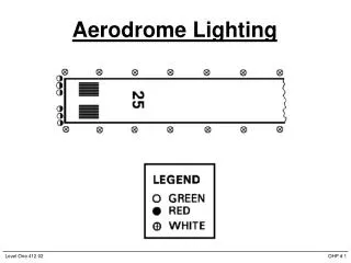
Taxiway Lighting Edge – Blue Centreline – Green Spacing – dependent on RVR requirements
Taxiway Edge Lighting • Omni-directional BLUE • Located as close to outside edge, or not more than 3m outside edge • Visible up 30° from horizontal, elevated but frangible • Shielded at intersections, exits or curves to minimize confusion • Spaced uniformly not more than 30m • On curve at radius divided by 4
Taxiway Centreline • Uni-/Bi-/Omni-directional GREEN • Show green and yellow from centreline to perimeter of ILS critical area • Visible to aircraft only in the vicinity of taxiway • Along centreline markings or offset max. 300mm • Spaced at max 30m along straight sections – except precision CAT III max 15m • Spaced on taxiway curve not to exceed 7.5m
Simple Approach Lighting System Where practicable installed for non-instrument and instrument non-precision runways used for night operations. Location/Configuration Extends out to 420m from threshold. Centreline lights spaced every 60m (30m optional) Single crossbar at 300m Lighting either single source or barrette
Precision Approach Cat 1 ALS Extends out to 900m from threshold. High intensity uni-directional white Lighting single source or barrette Centreline spacing 30m Crossbars spacing 150m
Precision Approach Cat 2,3 ALS Configuration as for CAT 1 ALS with the addition of side row barrettes from 300m to threshold spaced at 30m in line with centreline lights
VASIS • Visual Approach Slope Indicator System • T-VASIS dual sides runway • AT-VASIS single side of runway • PAPI Dual or single side of runway • APAPI • Red/White VASIS – no longer Annex 14 system
T-VASIS On path centre – wing-bar shows white Slightly high - fly down units progressively show white Grossly high - all fly down show white Slightly low – fly up units progressively show whit Grossly low – wing-bar and all fly up show red
PAPI - MEHT • Minimum Eye Height over Threshold on slope (MEHT) • Annex 14 – 2.12 AIP to contain nominal approach angle and MEHT • Annex 14 requires PAPI to be set to achieve minimum wheel clearance/ threshold for most demanding aircraft regularly using runway as per table 5-2
Apron Lights • Flood lights • Edge lights • Lead in Guidance Systems
Obstruction Lights • Required for obstructions that penetrate any obstacle limitation surface as defined in Annex 14 Chapter 4 – Appropriate Aeronautical Study first must be undertaken to ensure appropriate level of safety. • Also required marking of obstacles.
Obstruction Lighting Obstacles with height (Y) greater than 45m intermediate lights must be shown Light spacing (x) in accordance with Appendix 6 Number of levels of lights = N = Y (metres) X (metres)
Lighting Serviceability • 10.4.1 A light shall be deemed to be unserviceable when the main beam average intensity is less than 50 per cent of the value specified in the appropriate figure in Appendix 2. For light units where the designed main beam average intensity is above the value shown in Appendix 2, the 50 per cent value shall be related to that design value. • Category 1 85% serviceable • Category 2 & 3 95% serviceable