Download
1 / 45
490 likes | 690 Views
Manitou Springs High School. Electrical Systems for Robotics II. Electrical Systems for Robotics. Part I Fundamentals Hydraulic Analogy Alternating Current Direct Current Power Sources Power Devices Intro to Electrical Systems. Electrical Systems for Robotics. Part II

E N D
Manitou Springs High School Electrical Systems for Robotics II
Electrical Systems for Robotics • Part I • Fundamentals • Hydraulic Analogy • Alternating Current • Direct Current • Power Sources • Power Devices • Intro to Electrical Systems
Electrical Systems for Robotics • Part II • Electrical Systems • Components • Distribution • Wiring • Circuit Breakers • Fuses • Application to Robotics • Actuators – Motors, Solenoids • Sensors – Speed, Distance • Control System – Computer, Drive station
Robotics Electrical System Components • Electrical source • Battery • Electrical Distribution & Safety • Power Distribution Board • Fuses • Circuit Breakers • Wires & Connectors • Electrical Controllers • Relays • Solenoids • Speed Controllers • Electrical Loads • Actuators • Sensors • Control System
Electrical Source • Battery • Battery Charger
Battery Connections Series • A “series” system increases the voltage, but keeps the battery capacity (cranking amps, amp hours, reserve minutes, and minutes running time) the same • Therefore, two 12-volt batteries connected in series (POS to NEG, NEG to POS) will deliver 24 volts at the same rating as one battery • During recharge, each battery receives the same amount of current • e.g. if the charger is putting out 10 amps, both batteries are getting 10 amps.
Battery Connections Parallel • A “parallel” system increases the capacity available, but keeps the voltage the same • Therefore, two 12-volt batteries with 400 CCA, 110 R.C. and 65 Ah will deliver 12 volts, 800 CCA, 220 R.C. and 130 Ah. (Actually, since each battery’s load is lighter, the reserve capacity will more than double.) • During recharge, the current (amps) is split between the batteries. • The battery that is discharged the most will receive more current than the other until both are brought up to full charge.
Battery Connections Series/Parallel • A “series/parallel” system provides a combination of voltage and capacity for special applications. Note: Never mix different types and sizes of batteries in the same bank. • Dual Voltage • The illustration shows an arrangement that would supply 24 volts to a starter and 12 volts to the electronics (or vice versa) • To properly recharge, a sophisticated “battery isolator” should be installed. Otherwise, one battery will be continually overcharged and the other undercharged in a dual-voltage set-up. • IMPORTANT: Do not install any type of battery in a completely sealed box or enclosure. In the event of overcharging, the potentially explosive gasses must be allowed to escape.
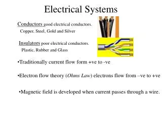
Electrical Distribution & Safety • Wires & Connectors • All wires are *not* created equal • Many different properties • Different conducting materials • Copper • Aluminum • Different wire construction • Solid • Stranded • Different Insulators • Polymers • Plastic • Cloth fabric (old homes) • Different colors • Has nothing to do with properties of wire itself • Is only an agreed upon ‘convention’ between affected parties • Red = ‘+’ = ‘Hot’, Black = ‘-’ = ‘Ground’
Electrical Distribution & Safety • Wires & Connectors • Different Diameters • Wire size -> Gauge • Different size wires can carry different size current • Why? • Resistivity – smaller wires resist carrying larger currents • However – using larger wires for all loads is not solution either • Higher cost • Higher weight • More difficult to work with than required • Select wires sized to job appropriately
Wire Gauge • American Wire Gauge (AWG) • A standardized wire gauge system used since 1857 • The diameters of round, solid, nonferrous, electrically conducting wire • The cross-sectional area of each gauge is an important factor for determining its current-carrying capacity
Wire Gauge • American Wire Gauge (AWG) • Increasing gauge numbers give decreasing wire diameters • Which is similar to many other non-metric gauging systems. • This gauge system originated in the number of drawing operations used to produce a given gauge of wire. • Very fine wire (for example, 30 gauge) required more passes through the drawing dies than did 0 gauge wire. • Manufacturers of wire formerly had proprietary wire gauge systems • The development of standardized wire gauges rationalized selection of wire for a particular purpose. • The AWG tables are for a single, solid, round conductor • The AWG of a stranded wire is determined by the total cross-sectional area of the conductor, which determines its current-carrying capacity and electrical resistance. • Because there are also small gaps between the strands, a stranded wire will always have a slightly larger overall diameter than a solid wire with the same AWG.
Wire Gauge • American Wire Gauge (AWG) • By definition, No. 36 AWG is 0.0050 inches in diameter, and No. 0000 is 0.4600 inches in diameter • The ratio of these diameters is 1:92 • There are 40 gauge sizes from No. 36 to No. 0000, or 39 steps.
Wire Gauge • American Wire Gauge (AWG) • Using this common ratio, wire gauge sizes vary geometrically according to the following formula: The diameter of a No. n AWG wire is:
Wire Gauge • American Wire Gauge (AWG) • The sixth power of this ratio is very close to 2, which leads to the following rules of thumb: • When the diameter of a wire is doubled, the AWG will decrease by 6. (e.g., No. 2 AWG is about twice the diameter of No. 8 AWG.) • When the cross-sectional area of a wire is doubled, the AWG will decrease by 3. (e.g., Two No. 14 AWG wires have about the same cross-sectional area as a single No. 11 AWG wire.) • Additionally, a decrease of ten gauge numbers, for example from No. 10 to 1/0, multiplies the area and weight by approximately 10 and reduces the resistance by a factor of approximately 10.
Wire Gauge • American Wire Gauge (AWG) When the cross-sectional area of a wire is doubled, the AWG will decrease by 3. (e.g., Two No. 14 AWG wires have about the same cross-sectional area as a single No. 11 AWG wire.) When the diameter of a wire is doubled, the AWG will decrease by 6. (e.g., No. 2 AWG is about twice the diameter of No. 8 AWG.)
Electrical Controllers • All current for entire robot flows from battery • Cumulative current of all electrical loads • Larger wire (conductor) • 6 AWG • Smaller current flows to lights, sensors • Smaller wire (conductor) • 20 AWG
Electrical Distribution & Safety Power Distribution Board • The PD Module is used to safely distribute battery power via thermal breakers and WAGO connectors. The PD also includes a set of power supplies for various devices. • Battery input voltage range of 6-15V • M6 shanks for battery connection • Sufficient copper mass and low-resistance distribution for use with a 120A main breaker supplying the module • 8 outputs that support up to 40A breakers • 12 outputs that support up to 30A breakers • 24V/1.5A boost supply with on-board 1.1A PTC for over-current protection (typically for powering a cRIO from National Instruments) • 5V/3A buck supply with integral over-current protection (typically for powering an Ethernet camera) • 12V/2A boost supply with on-board 2A PTC for over-current protection (typically for powering a WiFi adapter, the boost supply tracks battery voltage when the battery is fully charged and greater than 12V) • Reverse battery protection for the cRIO, WiFi, and Camera power supplies • LEDs for each power supply They light red if and only if there is a load present and either breaker is absent or the breaker is blown
Electrical Distribution & Safety • Connector Types • Aka ‘Terminals’ • Screw • Crimp • Solder • Solderingis a process in which two or more metal items are joined together by melting and flowing a filler metal (solder) into the joint, the filler metal having a lower melting point than the workpiece
Electrical Distribution & Safety Circuit Breakers • An automatically operated electrical switch designed to protect an electrical circuit from damage caused by overload or short circuit • An electrical circuit that allows a current to travel along an unintended path, often where essentially no (or a very low) electrical resistance is encountered • In electrical devices, unintentional short circuits are usually caused when a wire's insulation breaks down, or when another conducting material is introduced, allowing charge to flow along a different path than the one intended. • A common type of short circuit occurs when the positive and negative terminals of a battery are connected with a low-resistance conductor, like a wire. • With low resistance in the connection, a high current exists, causing the cell to deliver a large amount of energy in a short time. • A Circuit Breaker’s basic function is to detect a fault condition and, by interrupting continuity, to immediately discontinue electrical flow • Unlike a fuse, which operates once and then must be replaced, a circuit breaker can be reset (either manually or automatically) to resume normal operation. • Circuit breakers are made in varying sizes, from small devices that protect an individual household appliance up to large switchgear designed to protect high voltage circuits feeding an entire city.
Electrical Distribution & Safety • FRC Robots have 4 types of circuit breakers • Auto-reset breakers • 20 A • 30 A • 40 A • 120 A Main Breaker • Automotive style • Main switch for robot
Electrical Distribution & Safety Voltage Converters • A DC-to-DC converter is an electronic circuit which converts a source of direct current (DC) from one voltage level to another. It is a class of power converter • DC to DC converters are important in portable electronic devices such as robots, cellular phones and laptop computers, which are supplied with power from batteries primarily. • Such electronic devices often contain several sub-circuits, each with its own voltage level requirement different from that supplied by the battery or an external supply (sometimes higher or lower than the supply voltage) • Additionally, the battery voltage declines as its stored power is drained • Switched DC to DC converters offer a method to increase voltage from a partially lowered battery voltage thereby saving space instead of using multiple batteries to accomplish the same thing. • Most DC to DC converters also regulate the output voltage DC/DC Power Converter 12/24V to 5V
Electrical Controllers Relays • An electrically operated switch. • Many relays use an electromagnet to operate a switching mechanism mechanically, but other operating principles are also used. • Relays are used where it is necessary to control a circuit by a low-power signal (with complete electrical isolation between control and controlled circuits), or where several circuits must be controlled by one signal. • The first relays were used in long distance telegraph circuits, repeating the signal coming in from one circuit and re-transmitting it to another. Relays were used extensively in telephone exchanges and early computers to perform logical operations. • Solid-state relays (SSR) control power circuits with no moving parts • Uses a semiconductor device to perform switching. • Increasing long-term reliability. • Every solid-state device has a small voltage drop across it. • This voltage drop limits the amount of current a given SSR can handle. • The minimum voltage drop for such a relay is a function of the material used to make the device. • Solid-state relays rated to handle as much as 1,200 Amperes have become commercially available.
Electrical Controllers • Speed Controllers • Pulse-width modulation (PWM) is a digital technique for varying the amount of power delivered to an electronic component • By switching power on and off very fast the speed of a motor (or brightness of a light) can be controlled. • The simplest and most flexible PWM is generated by a microcontroller – as in on a robot.
PWM • The energy being sent to a load is measured in Duty Cycle • The ratio between the time the power source is switched on and switched off • At a Duty Cycle of 100%, the power is switched on all the time. • In contrast, a Duty Cycle of 0% means that the power is switched off all the time. • Those two states are equivalent to a manual switch which can be either in ON or OFF position • But cannot change rapdily between the two. • Now, a PWM controller does just that - it switches very rapidly between ON and OFF positions
Solenoids • Aka “Pneumatic solenoid valve” is a switch for routing air to any pneumatic device, usually an actuator, allowing a relatively small signal to control a large device. • Solenoids are the interface between electronic controllers and pneumatic systems
Electrical Loads • Actuators
Electrical Loads • Motors • Rotational drive and power • Primary Actuators • Rated for mechanical power • Usually attached to geared transmission mechanisms • Consume electrical power • Varying amps based on load and speed • Servos • Rotate partial turns and return • Lights • Pneumatic Cylinders • Quick, explosive movement & return • Sized by length of arm and bore of cylinder
Electrical Loads • Sensors • Give robots sensing capabilities to • See • Touch • Hear • Detect Movements • Rotations • Angles • Detect Distances • Detect Environmental Conditions • Temperature • Humidity • Altitude • All require a small amount of electrical power to operation • Are part of the power budget
Electrical Loads • FRC Sensors • Encoders – counts rotations • Used to measure speed • Limit switch – triggered when an actuator reaches a ‘limit; • Cameras – can see multiple ways • Visual • Infrared • Ultrasonic sensor – measures distance • Gyro – detects angle changes • Accelerometer – detects motion changes
Electrical Loads • Control System • The on-board brains of a robot • Consists of all elements that are required to perform logic operations on the robot • Based on information from • Driver • Pre-programmed algorithms • Sensor inputs • Actuator states • All elements consume power • Part of the power budget
Testing & Measurement • Digital Multimeter • Oscilloscope
Power Budget • Determine the power budget for an FRC robot built with the following components:
W = V x I (Watts = Volts X Current) • I = W/V (Current = Watts/Volts) • V = W/I (Volts = Watts/Current) • Robot battery provides 12 volts of power and 17 amp hours • Use CIM Motors for Chassis & Launcher subsystem • Indicated by the Black ‘Left’, ‘Right’, ‘Top’ & ‘Bottom’ motors • CIM Motor is rated at maximum power of 68 amps • Free current: 2.7 amps • Stall current: 133 amps • Use window motors for ‘Tilt’ & ‘Trigger’ • Use Fisher-Price motors for ‘Twist’, ‘Arm’ & ‘Pickup’ Example from Part I • How much power does the CIM motor use at maximum power in one hour? • Draws 68 amps • Driven by 12 volts • W = 68 * 12 = 816 watts • Calculate for each motor & device powered by battery • Add watts together • Determine how fast battery will drain • How fast will the battery drain at this rate? • Calculate the energy the battery has • E= (amp hour rating) x (average voltage of the battery) x (3600 seconds per hour) • E = 17 Ah * 12 volts X 3600 sec/hr = 734,400 joules energy within the battery • Calculate the drain time • Time (T) = (energy stored in the battery) / (total power drain) • T = 734,400 joules / 816 watts = 900 seconds = 15 minutes