Download
1 / 30
300 likes | 477 Views
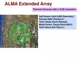
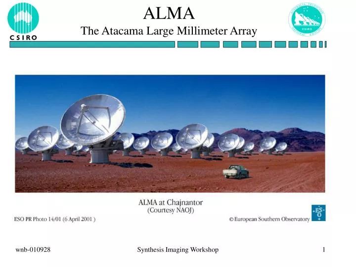
ALMA The Atacama Large Millimeter Array. ALMA site. 5 km altitude at the foot of the high Andes. ALMA telescopes (EU). ALMA telescopes (US). ALMA specifications. 64 antennas, at 5km height 12m diameter, 20 m, 0.6” in 9m/s wind arrays of 150m to 12km

E N D
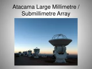
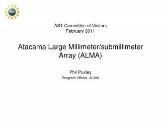
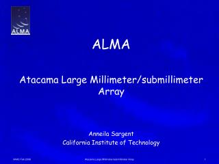
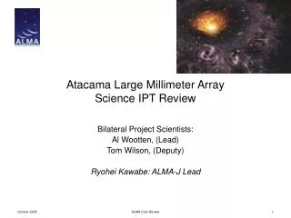
ALMAThe Atacama Large Millimeter Array Synthesis Imaging Workshop
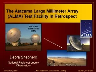
ALMA site 5 km altitude at the foot of the high Andes Synthesis Imaging Workshop
ALMA telescopes (EU) Synthesis Imaging Workshop
ALMA telescopes (US) Synthesis Imaging Workshop
ALMA specifications • 64 antennas, at 5km height • 12m diameter, 20 m, 0.6” in 9m/s wind • arrays of 150m to 12km • 10 bands in 31-950 GHz + 183 GHz WVR. Initially: • 86-119 GHz • 211-275 GHz • 275-370 GHz • 602-720 GHz • 8 GHz , dual polarisation, 4096 channels/IF (Note: varying numbers mentioned throughout project) • 600 M$US Synthesis Imaging Workshop
ALMA specifications • all bands online • any 1 + 0.5 bands accessible • filled (150m) to ring (12km) and log-spiral or ring • data rate: 1M visibilities/s average (= 6Mb/s average; 60Mb/s must be sustainable) • all data archived (raw + images) • AC (Compact or Complementary)A • 6-10 antennas of 6-8m diameter in ring or hexagon for short spacings Synthesis Imaging Workshop
Sensitivity goals At 50 deg elevation and best 25% weather for λ<1mm; best 75% for λ>1mm Synthesis Imaging Workshop
Other arrays (Courtesy Tony Wong) Synthesis Imaging Workshop
ALMA map Synthesis Imaging Workshop
ALMA local area Synthesis Imaging Workshop
ALMA topo Synthesis Imaging Workshop
ALMA barometer Synthesis Imaging Workshop
ALMA humidity Synthesis Imaging Workshop
Atmospheric transparency Synthesis Imaging Workshop
ALMA temperature Synthesis Imaging Workshop
ALMA wind direction Synthesis Imaging Workshop
ALMA wind speed Synthesis Imaging Workshop
ALMA bands (courtesy Wolfgang Wild) Synthesis Imaging Workshop
Noise regimes ALMA SKA-hi SKA-lo SKA-mid Temperaturein K 1. 10. 100. 1000. 0.01 0.1 1.0 10. 100. 1000. Frequency in GHz Synthesis Imaging Workshop
System noise source (courtesy Wolfgang Wild) Synthesis Imaging Workshop
Receiver optics (courtesy Wolfgang Wild) Synthesis Imaging Workshop
ALMA schedule • Proposed schedule: • 2 prototype (US and EU) antennas in August 2002 • 6-9 months delayed • January 2002: Construction (Phase 2) start • delayed due to US president budget stop for new projects • possible move of astronomy from NSF to NASA • future projects uncertain at the moment • April 2003 decision on antennas (+ 0.5 year?) • 2006 interim operations • 2011 full science operations Synthesis Imaging Workshop
ALMA status • Decisions: • ESO (+E) December 2001 (when and if US decision) • USA (+CA) Hopefully next budget • JP Contract signed in April 2001 • First talks about work division for 3 partners held in Paris • For computing 3rd partner adds 12% to cost • US proposes to cut project by 20% • ESO wants no cuts, at most 10% - accepted by all parties • JP still hopes to add extra bands; next correlator • JP also talking ACA • Fight for money started (e.g. software/computing is 32M$) by partners Synthesis Imaging Workshop
SKA 6cm HST ALMA Field-of-view SKA 20 cm 15 Mpc at z = 2 Primary beam from 180” (30GHz) – 6” (900GHz) Synthesis Imaging Workshop
ALMA mosaicing Many objects to be observed by ALMA, such as nearby galaxies and molecular clouds in our own galaxy, will be diffuse and much larger than ALMA’s primary beam. Mosaicing will have to be done. However, mosaicing places stronger constraints on the antennas than single pointing interferometry. Why not build a 70~m single dish to observe these big sources? Mosaicing is faster than single dishobservations, mainly because of the multiple synthesized beams which can be formed within each primary beam. Synthesis Imaging Workshop
Mosaicing limits Pointing: Because the emission spans beyond a single primary beam in mosaicing, small antenna pointing errors can have a large effect on the observed flux of a feature which liesnear the half power point of the beam. Pointing accuracy of about 1/25th of the beamwidth will permitmosaics of about 1000:1 dynamic range (linear with ν). Surface Accuracy: Surface errors will scatter radiation into the primary beam sidelobes, and unmodeled primary beam sidelobe structure will limit the quality of mosaic images.While surface accuracy of 1/16th of a wavelength only degrades the dish efficiency by a factor of 2 from Ruze losses, 1000:1 dynamic range mosaics will require surface accuracies of about 1/40th of a wavelength (quadratic with ν). Synthesis Imaging Workshop
Mosaicing limits Getting Very Short Spacings: The homogeneous array concept requires that the antennas be fairly close together (ie, 1.3 times the dish diameter for zenith observations) to beable to measure spatial frequencies in the range of the dish diameter. However, the antennas can actually smack into each other if theseparation is less than about 1.5 dish diameters (depending upon the design). To improve the short spacing capabilities (i.e. the large scale structure) the ACA has been proposed with about 10 antennas of about 6m diameter. Synthesis Imaging Workshop
Phase stability Inhomogeneously distributed water vapour results in different electrical path lengths above the different antennas, or phase error. The phase errors scatter flux, limiting the dynamic range, and also cause decorrelation, which artificially decreases the source amplitude. The initial calibration is planned with a 183GHz spectral line WVR (cf the ATCA 22GHz WVR). Synthesis Imaging Workshop
Calibration possibilities • The complete ALMA array, with 64 telescopes has about 2000 baselines, many more than any other existing telescope. This enables the use of algorithms different from used in today’s mm instruments. E.g.: • use of redundant and quasi-redundant baselines • use of parameterized models for the phase errors across telescope aperture • use of pointing correction model parameters Synthesis Imaging Workshop
ALMA With NGST, ALMA and SKA in the second decade of this century the electro-magnetic spectrum from 1μm till 10m will be available to the next generation of astronomers with a resolution of about 0.02”, and high sensitivities. Synthesis Imaging Workshop