Download

1 / 24
250 likes | 266 Views
Lecture 19 Land grading – Land levelling design methods - plane method. Land grading is reshaping of the field surface to a planned grade To make a suitable field surface to control flow of water To check soil erosion and To provide for surface drainage.

E N D
Lecture 19 Land grading – Land levelling design methods - plane method
Land grading is reshaping of the field surface to a planned grade • To make a suitable field surface to control flow of water • To check soil erosion and • To provide for surface drainage. • Irrigated areas benefit greatly from land grading since the ground in its natural state is seldom suited for the efficient application of water
In low rainfall areas, land grading • Produces a smooth uniform land surface, • Reduces runoff and induces infiltration of rain fall • Assures even moisture distribution. • On sloping ground, levelling eliminates small depressions, cuts and furrows which leads to concentration of runoff. • Proper land grading, coupled with surface drainage measures, reclaim unproductive poorly drained areas.
Phases of Land levelling operations • Rough grading • Land levelling • Land smoothing.
Criteria for land grading are influenced by • The characteristics of the soil profile, • Prevailing land slope, • Rainfall characteristics, • Cropping pattern, • Methods of irrigation, • Other special features of the site • The preferences of the farmer.
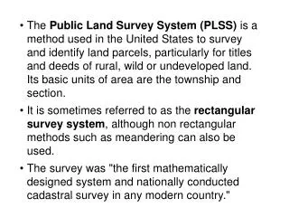
LAND CLEARING Prior to making the land grading survey, it is advantageous to remove heavy vegetative growth from the land. Land clearing consists of removing some or all of the trees, bush, vegetation, trash and boulders and all roots.
A well-designed irrigation system delivers the required amount of water to all parts of the area to be irrigated at the required rate without damage to the soil or excessive loss of water. • The topography is a major factor in selecting • The method of irrigation • Estimating the number and kind of water control structures needed • Determining the need for land levelling • The relative elevations of the source and the area to be irrigated • The drainage outlets
Land levelling design methods • Plane method • Profile method • Plan inspection method • Contour adjustment method
Plane method Procedure: • Determine the centroid of the field • Determine the average elevation of the field • Compute the slope of the plane of best fit • Compute the formation levels, cuts and fills • Determine the cut-fill ratio
Determining the centroid of the field The centroid of a rectangular field is located at the point of intersection of its diagonals. The centroid of a triangular field is located at the intersection of the lines drawn from its corners to the midpoints of the opposite sides. To determine the centroid of irregular fields, the area is divided into rectangles and right-angled triangles. The centroid is located by computing moments about two reference lines at right angles o each other.
Determine the average elevation of the field Adding the elevations of all grid points in the field and dividing the sum by the number of point give the average elevation.
Locate the centroid and fix its elevation as mean of the field
Compute the slope of the plane of best fit. The slope of any line in the x or y direction on the plane which fits the natural ground surface, can be determined by the least squares method. in which S=slope of line in a p1ane, dimensionless* D= distance from the reference line, m H= elevation of the grid point, m n = number of grid points
Compute the formation levels, cuts and fills: With the elevation of the centroid determined, the formation level of any point (the elevation which the point should attain after land grading operation) may be determined, using the computed or assumed values of Sx and Sy.
Mark the existing and computed elevation on grid points and compute cut/ fill
Computation of earthwork volumes of field : L² ∑ C² Vc = ---------------------- 4(∑ C + ∑ F) L² ∑ F² Vf = -------------------------- 4 (∑ C + ∑ F) In which, Vc = Volume of cut, m³ Vf = Volume of fill, m³ L = Grid spacing, m ∑ C = Sum of cuts on four corners of a grid square, m ∑ F = Sum of fills on four corners of a grid square, m
PROFILE METHOD, Essentially it consists of a trail and error method of adjusting grades on plotted profiles until the irrigation criteria are met with and the earthwork balance is attained.
PLAN INSPECTION METHOD The grid point elevations are noted on the plan, and the design grade elevations are determined by inspection after the careful study of the topography. It is largely a trial and error procedure. In selecting the elevations formation level the designer must simultaneously consider the down field slope, cross slope, earth work balance and haul distance. The desired cut fill ratio and volumes of earthwork are estimated from the summation of cuts and fills. The grades are frequently adjusted to obtain favourable earthwork balance and to maintain the down field and cross slopes within safe limits.
CONTOUR ADJUSTMENT METHOD The contour adjustment method of land levelling designs consists of trial and error adjustments of the contour lines on a plan map. The method is specially adapted to the smoothening of steep lands that have to be irrigated. A contour map is drawn and the proposed ground surface is shown on the same map by drawing new contour lines. The uniformity of downfield slope is controlled by the uniformity of the horizontal spacing between contours, and the cross slopes can be examined by scaling the distance between contours at right angles to the direction of irrigation.