Download
1 / 21
230 likes | 443 Views
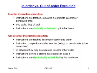
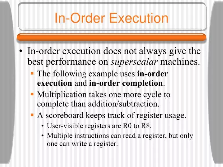
In-Order Execution. In-order execution does not always give the best performance on superscalar machines. The following example uses in-order execution and in-order completion . Multiplication takes one more cycle to complete than addition/subtraction.

E N D
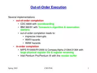
In-Order Execution • In-order execution does not always give the best performance on superscalar machines. • The following example uses in-order execution and in-order completion. • Multiplication takes one more cycle to complete than addition/subtraction. • A scoreboard keeps track of register usage. • User-visible registers are R0 to R8. • Multiple instructions can read a register, but only one can write a register.
In-Order Execution • The scoreboard has a small counter for each register telling how many times that register is in use by currently-executing instructions. • If a maximum of, say, 15 instructions may be executing at once, then a 4-bit counter will do. • The scoreboard also has a counter to keep track of registers being used as destinations. • Since only one write at a time is allowed, these registers can be 1-bit wide. • In a real machine, the scoreboard also keeps track of functional unit usage.
In-Order Execution • We can notice three kinds of dependencies which can cause problems (instruction stalls): • RAW (Read After Write) dependence • WAR (Write After Read) dependence • WAW (Write After Write) dependence • In a WAR dependence, one instruction is trying to overwrite a register that a previous instruction may not yet have finished reading. A WAW dependence is similar.
In-Order Execution • In-order completion is important as well in order to have the property of precise interrupts. • Out-of-order completion leads to imprecise interrupts (we don’t know what has completed at the time of an interrupt - this is not good). • In order to avoid stalls, let us now permit out-of-order execution and out-of-order retirement.
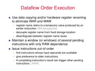
Out-of-Order Execution • The previous example also introduces a new technique called register renaming. • The decode unit has changed the use of R1 in I6 and I7 to a secret register, S1, not visible to the programmer. • Now I6 can be issued concurrently with I5. • Modern CPUs often have dozens of secret registers for use with register renaming. • This can often eliminate WAR and WAW dependencies.
Speculative Execution • Computer programs can be broken up into basic blocks, with each basic block consisting of a linear sequence of code with one entry point and one exit. • A basic block does not contain any control structures. • Therefore its machine language translation does not contain any branches. • Basic blocks are connected by control statements. Programs in this form can be represented by directed graphs.
Speculative Execution • Within each basic block, the reordering techniques seen work well. • Unfortunately, most basic blocks are short and there is insufficient parallelism to exploit. • The next step is to allow reordering to cross block boundaries. • The biggest gains come when a potentially slow operation can be moved upward in the graph to get it going earlier. Moving code upward over a branch is called hoisting.
Speculative Execution • Imagine that all of the variables of the previous example except evensum and oddsum are kept in registers. • It might make sense to move their LOAD instructions to the top of the loop, before computing k, to get them started early on, so the values will be available when they are needed. • Of course only one of them will be needed on each iteration, so the other LOAD will be wasted.
Speculative Execution • Speculative execution introduces some interesting problems. • It is essential that none of the speculative instructions have irrevocable results because it may turn out later that they should not have been executed. • One way to do this is to rename all the destination registers to be used by speculative code. In this way, only scratch registers are modified.
Speculative Execution • Another problem arises if a speculatively executed instruction causes an exception. • A LOAD instruction may cause a cache miss on a machine with a large cache line and a memory far slower than the CPU and cache. • One solution is to have a special SPECULATIVE-LOAD instruction that tries to fetch the word from the cache, but if it is not there, just gives up.
Speculative Execution • A worse situation happens with the following statement: if (x > 0) z = y/x; • Suppose that the variables are all fetched into registers in advance and that the (slow) floating-point division is hoisted above the if test. • If x is 0, the resulting divide-by-zero trap terminates the program even though the programmer has put in explicit code to prevent this situation. • One solution is to have special versions of instructions that might cause exceptions.
Core i7’s Sandy Bridge Microarchitecture The block diagram of the Core i7’s Sandy Bridge microarchitecture.
Core i7’s Sandy Bridge Pipeline (1) A simplified view of the Core i7 data path.
Core i7’s Sandy Bridge Pipeline (2) • Scheduler queues send micro-ops into the 6 functional units: • ALU 1 and the floating-point multiply unit • ALU 2 and the floating-point add/subtract unit • ALU 3 and branch processing and floating-point compare unit • Store instructions • Load instructions 1 • Load instructions 2
OMAP4430’s Cortex A9 Microarchitecture The block diagram of the OMAP4430’s Cortex A9 microarchitecture.
OMAP4430’s Cortex A9 Pipeline (1) A simplified representation of the OMAP4430’s Cortex A9 pipeline.
OMAP4430’s Cortex A9 Pipeline (2) A simplified representation of the OMAP4430’s Cortex A9 pipeline.
Microarchitecture of the ATmega168 Microcontroller The microarchitecture of the ATmega168.