Download
1 / 7
70 likes | 240 Views
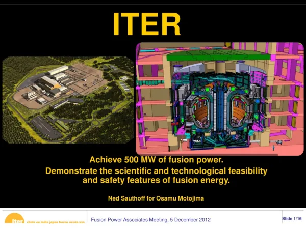
Introduction Prediction of ITER loads and T retention A. Loarte. Specification of ITER Loads. Specification of ITER loads has been reviewed during ITER Design Review update to take into account present physics understanding

E N D
IntroductionPrediction of ITER loads and T retentionA. Loarte Alberto Loarte 10th ITPA Divertor and SOL Physics Group Avila – Spain 7/10 – 1 – 2007 1
Specification of ITER Loads • Specification of ITER loads has been reviewed during ITER Design Review update to take into account present physics understanding • Particle/Power Fluxes to wall during diverted operation • Redefinition of divertor controlled ELM loads • Update of ELM divertor and wall power fluxes • Update of disruption and VDE thermal loads • Update of disruption and VDE EM loads • etc. Revised load specifications will be used to redesign details of ITER PFCs (main wall) Advice from ITPA required Uncertainties in load specifications is considerable judgment to specify reasonable and non-fluctuating values Alberto Loarte 10th ITPA Divertor and SOL Physics Group Avila – Spain 7/10 – 1 – 2007 2
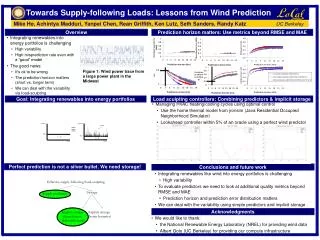
Evaluation of T retention in ITER • T retention is one of the key drivers for plasma facing materials choice in ITER PFM foreseen strategy based on present understanding of PWI in ITER Change of CFC to W divertor to minimise T retention • Prediction of T retention in ITER is a complex and uncertain • Uncertain plasma fluxes and conditions • ITER-specific issues (high Tsurf/Gplasma, n-irradiation, etc.) • Formation of mixed-materials • etc. Determination of fuel retention for ITER on present understanding, on-going R&D and Hydrogen phase results crucial to decide on best timing for change of divertor plasma materials in ITER programme Alberto Loarte 10th ITPA Divertor and SOL Physics Group Avila – Spain 7/10 – 1 – 2007 3
Lipschultz QDT = 10 steady plasma loads (I) • All divertor tomakaks measure plasma particle fluxes (II B) to the main wall • Extrapolated plasma flux to the main wall in ITER 1.0 - 5 .0 1023 s-1 (1-5 % of Gdiv) Lipschultz IAEA 2000 Alberto Loarte 10th ITPA Divertor and SOL Physics Group Avila – Spain 7/10 – 1 – 2007 4
LaBombard NF 2004 QDT = 10 steady plasma loads (II) • Plasma fluxes predominantly on outer side of first wall • Corresponding maximum IIB power densities up to : 5 MWm-2 (Upper X- point) to 1 MWm-2 near outer midplane and 0.4 MWm-2 near inner midplane Alberto Loarte 10th ITPA Divertor and SOL Physics Group Avila – Spain 7/10 – 1 – 2007 5
0.5 1.0 1.5 energy density / MJm-2 significantPAN fibreerosionafter 50 shots PAN fibreerosion offlat surfacesafter 100 shot PAN fibreerosionafter 10 shots erosion startsat PFC corners negligibleerosion CFC divertor target lifetime 20000 ELMs Tolerable ELM size QSPA experiments on NB31 targets show Tolerable ELM energy density 0.5 MJm-2 + no broadening + 2:1 in/out asymmetry DWELM ~ 1MJ fELM ~ 20-40 Hz 8000-16000 ELMs/QDT=10 shot Alberto Loarte 10th ITPA Divertor and SOL Physics Group Avila – Spain 7/10 – 1 – 2007 6
Wall ELM loads Wall ELM power/particle deposition starting to be characterised/understood extrapolation to ITER uncertain Uncontrolled ELMs in ITER DWELM = 20 MJControlled ELMs in ITER DWELM = 1.0 MJ Model by W. Fundamenski and R. Pitts Uncontrolled ELMs DWELM,wall = 2-4 MJControlled ELMs DWELM,wall = 0.05-0.1 MJ tELM,wall ~ ½ tELM,divertor • AIIELM < Afil ~ Nfildpoldr ~ 10 * 0.25 * 0.1 = 0.25 m-2 (A. Kirk) • Uncontrolled ELMs EIIELM > 8-16 MJm-2 (<qII,ELM> ~ 8-32 MWm-2 ) & Ewall,ELM (4o) ~ 0.6- 1.1 MJm-2 • Controlled ELMs EIIELM > 0.2-0.4 MJm-2 (<qII,ELM> ~ 4-16 MWm-2 ) & Ewall,ELM (4o) ~ 0.01-0.03 MJm-2 Alberto Loarte 10th ITPA Divertor and SOL Physics Group Avila – Spain 7/10 – 1 – 2007 7