Download
1 / 31
320 likes | 703 Views
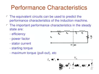
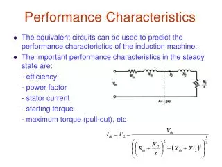
Performance Characteristics. The equivalent circuits can be used to predict the performance characteristics of the induction machine. The important performance characteristics in the steady state are: - efficiency - power factor - stator current - starting torque

E N D
Performance Characteristics • The equivalent circuits can be used to predict the performance characteristics of the induction machine. • The important performance characteristics in the steady state are: - efficiency - power factor - stator current - starting torque - maximum torque (pull-out), etc
Performance Characteristics Eqn. X
Performance Characteristics *eqn. X At high slip At low slip • At low slip, torque proportional to slip s • At high slip, torque inverse proportional to slip
Note if approximate circuit is used to get the equation of torque, then
T – N Single frequency characteristic -Ns 2 • Select one frequency () • Select V1 • Varies s ( at particular s, get T) • Repeat for other s to get T
T – N Single frequency characteristic • As slip is increased from zero (synchronous), the torque rapidly reaches the maximum. Then it decreases to standstill when the slip is unity. • At synchronous speed, torque is almost zero. • At standstill, torque is not too high, but the current is very high. Thus the VA requirement of the IM is several times than the full load. Not economic to operate at this condition. • Only at “low slip”, the motor current is low and efficiency and power factor are high.
Maximum Torque Differentiate eqn. dT/ds, and equate to zero If R1 small Increase R2, increase slip max, increase staring torque If R1 small Varying R2
Maximum Torque • Maximum air gap power transfer occurs at impedance matching principle – Another approaches • Rext to be added to produce Tmax at starting, ie at s = 1 is R ext
Current and Power Factor Stator current vs. speed Power factor vs. speed
Efficiency (1-s)Pag sPag Efficiency vs. speed *To get Max. efficiency, s must be very low Internal efficiency
Power Flow 0 < s < 1 0 < s s > 0
Example 4* A three-phase 460 V, 1740 rpm, 60 Hz 4-pole wound rotor induction star connected motor has the following parameter/phase: R1 = 0.25 , R2’ = 0.2 , X1 = X2’= 0.5 , Xm = 30 The rotational losses are 1700 W. With the rotor terminal short circuited, find: a) i) Starting current when started on full load ii) Starting torque b) i) Full load slip ii) Full-load current iii) Full-load power factor iv) Ratio of starting current to full load current v) Full-load torque vi) Internal efficiency and motor efficiency at full load c) i) Slip at maximum torque ii) Maximum Torque d) How much external resistance/phase should be connected in the rotor circuit so that maximum torque occurs at start? l Sol- pg13 Sen 241
N2 N1 Example 5 A three-phase 460 V, 60 Hz 6 -pole wound rotor induction motor drives a constant load of 100 N-m at speed of 1140 rpm when the rotor terminal is short-circuited. It requires to reduce speed to 1000 rpm by inserting resistance in rotor circuit. Determine the value of resistance if the rotor winding resistance / phase is 0.2 ohms. Neglect rotational losses. The stator to rotor turn ratio is unity. l Since the developed torque Tm = load torque TL R2 +R2ext R2 Sol_pg14 TL Sen 244
By changing the impedance (R) connected to the rotor circuit, the speed/current and speed/torque curves can be altered. Used primarily to start a high inertia load or a load that requires a very high starting torque across the full speed range with relatively low current from zero speed to full speed Wound Rotor Slip ring
Example 6 • The following test results are obtained from a three-phase, 100hp, 460 V, eight-pole, star connected squirrel-cage induction machine. No load test: 460 V, 60 Hz, 40 A, 4.2 kW Blocked-rotor test: 100 V, 60 Hz, 140 A, 8 kW Average dc resistance between two stator terminals is 0.152 Ω. (a) Determine the parameters of the equivalent circuit. (0.076 Ω, 0.195 Ω, 6.386 Ω, 0.195 Ω, 0.062 Ω). (b) The motor is connected to a three-phase , 460 V, 60 Hz supply and runs at 873 rpm. Determine the input current, input power, air gap power, rotor copper loss, mechanical power developed, output power, and efficiency of the motor. ( 127.9/-27o A, 90.82 kW, 87.09 kW, 2.613 kW, 84.48 kW, 80.64 kW, 88.79 %) Sol_pg16 Sen 282 (pb 5.6)
Classes of Squirrel-Cage Motor • To meet the various starting and running requirements of a variety of industrial applications, several standard ( T vs. N) designs of squirrel-cage motors are available from manufacturer’s stock. • The most significant design variable in these motors is the effective resistance of the rotor cage circuit ( for wound rotor)
Class A Motors • Characterized by normalstarting torque, high starting current and low operating slip. • Low rotor circuit resistance and therefore operate efficiently with a low slip (0.005<s<0.015) at full load. • Suitable for applications where the load torque is low at start (such as fan or pump) so that full speed is achieved rapidly, thereby eliminating the problem of overheating during starting. • In larger machines, low voltage starting is required to limit the starting current.
Class B Motors • Characterized by normal starting torque, low starting current and low operating slip. • The starting current is about 75 % of that for class A. • The starting current is reduced by designing for relatively high leakage reactance by using either deep-bar rotors or double- cage rotors. • The full load slip and efficiency are as good as those of class A motors. • Good general-purpose motors and have a wide variety of industrial applications. Suitable for constant speed drives. • Examples are drives for fans, pumps, blowers, and motor-generator sets.
Class C Motors • Characterized by high starting torque and low starting current. • A double-cage rotor is used with higher rotor resistance than is found in class B motors. • The full-load slip is somewhat higher and the efficiency lower than for class A and class B motors. • Class C motors are suitable for driving compressors, conveyors, crushers, and so forth.
Class D Motors • Characterized by high starting torque, low starting current and high operating slip. • The torque-speed characteristic is similar to that of a wound-rotor motor with some external resistance connected to the rotor circuit. • The full-load operating slip is high (8 to 15 %), and therefore the running efficiency is slow. • The high losses in the rotor circuit require that the machine be large (and hence expensive) for a given power. • Suitable for driving intermittent loads requiring rapid acceleration and high impact loads. • In the case of impact loads, a flywheel is fitted to the system which delivers some of its kinetic energy during the impact.
Speed Control • Pole Changing • Line Voltage Control • Line Frequency Control • Constant-slip Frequency Operation • Closed-loop Control • Constant-Flux Operation • Constant-current Operation • Rotor Resistance Control • Rotor Slip Energy Recovery
Pole changing Synchronous speed change with changes number of poles (change the stator winding/coil connection) Discrete step change in speed/ expensive Speed control of induction machine Given a load T–N characteristic, the steady-state speed can be changed by altering the profile of T–N of the motor: Rotor Resistance control For wound rotor only Variable line voltage (amplitude), variable frequency . Most popular method . Using power electronics converter . Operated at low slip frequency Variable line voltage (amplitude), frequency fixed Torque V2 E.g. using 3-phase autotransformer (variac) or solid state controller Slip becomes high as voltage reduced – low efficiency
Variable line voltage, fixed frequency V= 1pu V= 0.71pu Fan (TL) load V= 0.25pu
Auto Transformer Voltage Control Solid State Voltage Control Closed Loop Operation Voltage Control
Rotor resistance Control Open Loop Control Scheme Closed Loop Control Scheme
n Control both V and freq, f IM Supply 3-phase pwm Inverter Rectifier and Filter Typical IM Drive System - Variable voltage, variable frequency PWM Inverter
VSI Rectifier 3-phase supply IM C f Pulse Width Modulator Ramp V + s* VVVF, Constant V/f – open-loop
Example Final • Question 4 • Explain briefly three methods for controlling the speed of an induction motor. (6 marks) • (b) Draw a typical torque-speed characteristic of an induction motor and label key quantities. (3 marks) • (c) A three-phase, 415 V, 1450 rpm, 50 Hz, four-pole wound-rotor induction motor has the following parameters per phase: • R1 = 0.25 , R2’ = 0.2 • X1 = X2’ = 0.5 , Xm = 30 • The rotational losses are 1700 W. With the rotor terminals short-circuited, determine: • (i) Starting current when started direct on full voltage. (4 marks) • (ii) Starting torque. (4 marks) • (iii) Full-load current. (4 marks) • (iv) Full-load torque. (4 marks) SEMESTER 1 SESI 2007/2008 eg 5.4 pg 241
Example • QUESTION 4 • (a) Explain the working principle of a three-phase induction machine on the basis of magnetic fields. • Show through a power flow diagram, how electrical power input is converted into mechanical power output in an induction motor. • (c) A 3 phase , 415 V, 1450 rpm, 50 Hz, four-pole wound rotor induction motor has the following Thevenin’s equivalent circuit parameters per phase: • Vth = 236 V Rth = 0.25 W • Xth = 0.5 W X2 = 0.5 W R2’ = 0.2 W • The motor drives a constant load of 100 Nm at rated speed when the rotor terminals are short-circuited. Neglect rotational losses. • (i) Draw the Thevenin’s equivalent circuit of induction machine. • (ii) How much external resistance per phase should be connected in the rotor circuit so that maximum torque occurs at start-up? • (iii) It is required to reduce the speed of the motor to 1400 rpm by inserting resistance in the rotor circuit. How much external resistance per phase should be connected in the rotor circuit? • (iv)Draw torque-speed characteristics of the motor and load to show the conditions in (iii) with and without external rotor resistance. SEMESTER 1 SESI 2008/2009 Sol_pg31