Download

1 / 43
430 likes | 528 Views
Minimum-Layer Drawings of Trees. Debajyoti Mondal Md. Jawaherul Alam Md. Saidur Rahman. Graph Drawing and Information Visualization Laboratory Department of Computer Science and Engineering Bangladesh University of Engineering and Technology (BUET) Dhaka-1000, Bangladesh.

E N D
Minimum-Layer Drawings of Trees DebajyotiMondal Md. JawaherulAlam Md. SaidurRahman Graph Drawing and Information Visualization Laboratory Department of Computer Science and Engineering Bangladesh University of Engineering and Technology (BUET) Dhaka-1000, Bangladesh
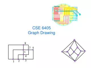
Layered Drawing of Trees a h g b a h i c g c b i j j d e f f d e A Tree T A layered drawing of T Each vertex is drawn as a point on some horizontal line and each edge is drawn as a straight line segment. WALCOM 2011, New Delhi, India
Minimum-Layer Drawing of Trees a h b a h i g c g c b 4 j i j f d e d e f j g c b i a g c b h i 2 h f a d e j 3 A minimum-layer drawing of T f d e A layered drawing of T is a minimum-layer drawing of T, if the number of layers used in the drawing is the minimum. WALCOM 2011, New Delhi, India
Motivation: Layout Design of Standard Cell • Visualization of • Organizational charts • Software class hierarchies • Phylogenetic evolutions • Programming language parsing Minimize the number of rows in the layout WALCOM 2011, New Delhi, India
Previous Works Each edge is between the vertices on adjacent layers Each path from the root is a y-monotone polyline WALCOM 2011, New Delhi, India
Some Minimum-Layer Drawings c a e b a c d e d b a a c b b c WALCOM 2011, New Delhi, India
Non-triviality for General Trees r r Observation: The drawing of some subtrees are packed into the drawing of some other subtrees. WALCOM 2011, New Delhi, India
Let’s try to draw from scratch 1 9 39 2 10 11 13 14 6 7 8 3 4 5 20 12 17 19 18 16 15 36 37 38 30 32 34 35 21 31 22 23 33 24 25 26 27 28 29 21 L21 = [1] A single vertex tree requires one layer in its minimum layer drawing. The subtree rooted at vertex 21 takes one layer. Thus we associate a label L21 = [1] with vertex 21. WALCOM 2011, New Delhi, India
Let’s try to draw from scratch 1 9 39 2 10 11 13 14 6 7 8 3 4 5 20 12 17 19 18 16 15 15 36 37 38 30 32 34 35 21 31 22 23 33 24 25 26 27 28 29 21 22 23 L15 = [2] [Suderman, 2005] Let T bea tree with three subtrees where each of these subtrees takes k layers in its layered drawing. Then any layered drawing of T requires at least k+1layers. WALCOM 2011, New Delhi, India
Let’s try to draw from scratch 1 2 9 39 10 11 3 4 5 13 14 6 7 8 20 12 17 19 18 16 15 36 37 38 30 32 34 35 21 31 22 23 33 24 25 26 27 28 29 L13 = [3] 13 15 16 17 21 22 23 29 24 25 26 27 28 We draw this subtree in 3-layers and 3-layers are also necessary for its layered drawing by, the previous argument of Suderman. WALCOM 2011, New Delhi, India
Let’s try to draw from scratch 1 2 9 39 10 11 3 4 5 13 14 6 7 8 20 12 17 19 18 16 15 36 37 38 30 32 34 35 21 31 22 23 33 24 25 26 27 28 29 L10 = [3] 13 14 10 15 16 17 20 19 18 36 37 38 21 30 22 23 29 24 25 32 34 35 26 27 28 31 33 Since we do not want to increase layers, we put vertex 10 in between 13 and 14. WALCOM 2011, New Delhi, India
Let’s try to draw from scratch 1 2 9 39 11 10 3 4 5 13 14 6 7 8 12 20 17 19 18 16 15 36 37 38 30 32 34 35 21 31 22 23 33 24 25 26 27 28 29 L10 = [3] 13 14 10 15 16 17 20 19 18 36 37 38 21 30 22 23 29 24 25 32 34 35 26 27 28 31 33 At this step vertex 10 does not have visibility to its right or left, i.e, it cannot see any point p to its left or right which lies outside of the bounding box of drawing. WALCOM 2011, New Delhi, India
Let’s try to draw from scratch 1 2 9 39 11 10 3 4 5 13 14 6 7 8 12 20 17 19 18 16 15 36 37 38 30 32 34 35 21 31 22 23 33 24 25 26 27 28 29 L10 = [3] 13 14 10 p 15 16 17 20 19 18 36 37 38 21 30 22 23 29 24 25 32 34 35 26 27 28 31 33 At this step vertex 10 does not have visibility to its left or right, i.e, it cannot see any point p to its left or right which lies outside of the bounding box of the drawing. WALCOM 2011, New Delhi, India
Let’s try to draw from scratch 1 2 9 39 11 10 3 4 5 13 14 6 7 8 12 20 17 19 18 16 15 36 37 38 30 32 34 35 21 31 22 23 33 24 25 26 27 28 29 13 14 10 15 16 17 20 19 18 Layers to continue drawing 36 37 38 21 30 22 23 29 24 25 32 34 35 26 27 28 31 33 We say that this drawing has become saturated. (no more subtrees that requires at least 3 layers cannot be drawn within this drawing) Any further drawing should use the space below vertex 10. WALCOM 2011, New Delhi, India
Let’s try to draw from scratch 1 2 9 39 11 10 3 4 5 13 14 6 7 8 12 20 17 19 18 16 15 36 37 38 30 32 34 35 21 31 22 23 33 24 25 26 27 28 29 13 14 10 15 1 11 12 9 6 7 8 16 2 17 20 19 18 39 3 4 5 36 37 38 21 30 22 23 29 24 25 32 34 35 26 27 28 31 33 We have two saturated drawings; one is for vertex 10 and the other is for vertex 1. These two drawings forms a partition P of the tree. P has two elements (red and blue). WALCOM 2011, New Delhi, India
Let’s try to draw from scratch What happens if we continue drawing further and the layers available are not sufficient? L1 = [3,2] 1 2 9 39 11 10 3 4 5 13 14 6 7 8 12 20 17 19 18 16 15 36 37 38 30 32 34 35 21 31 22 23 33 24 25 26 27 28 29 13 14 10 15 1 11 12 9 6 7 8 16 2 17 20 19 18 39 3 4 5 36 37 38 21 30 22 23 29 24 25 32 34 35 26 27 28 31 33 We associate a label L1 = [3,2] with the root of the tree. Observe that the partition of the tree contains |L1| = 2 elements, where one element has 3-layer drawing and the other element has 2-layer drawing. WALCOM 2011, New Delhi, India
Let’s try to draw from scratch r b La= [3, 2] Lb= [4, …..] a B A r b B a The label of the root of SubtreeB contains 4. Therefore, B requires at least 4 layers. Draw A with one more layer so that vertex a obtains right visibility (can see r). WALCOM 2011, New Delhi, India
Let’s try to draw from scratch r Such modifications are possible if the drawings of the components are root visible drawings (root is visible from a point above or below the bounding box of the drawing) For example, p and q are visible from n, which lies above the blue bounding box. b n B a m r b a n m q p B Find the path from a to the first vertex on the topmost layer in the drawing of A. Put the vertices on the path on the layer of vertex b. Draw the components connected with the path below the path. WALCOM 2011, New Delhi, India
Algorithm Outline Given a tree T, find a minimum-layer root-visible drawing of T taking an arbitrary vertex r as a root of T. [O(n) time] Compute all the minimum-layer root visible drawings of T taking each vertex of T as a root. The root visible drawings with the minimum number of layers is the minimum-layer drawing of T. [O(n2) time] The proof follows from the fact that, In any layered drawing of a tree, at least one vertex is visible from a point above or below the bounding box of the drawing. WALCOM 2011, New Delhi, India
Algorithm Outline We can choose a suitable vertex x in O(n) time such that minimum-layer root visible drawing taking x as a root of T is a minimum-layer drawing of T. Thus the running time becomes O(n) in total. How can we obtain a minimum-layer root visible drawing? WALCOM 2011, New Delhi, India
Minimum-Layer Root Visible Drawing Compute a partition and a labelof the tree from the partitions and labels of the subtrees in a bottom-up approach. Once the partition is computed, draw the corresponding partition. Computing of a partition is broken down into four cases depending on the labels of the subtrees. WALCOM 2011, New Delhi, India
Illustration of Cases L(r) = f(L(r1), L(r2), … , L(rd)) r r2 r1 rd r3 r4 Si is the smallest integer in L(ri) Bi is the largest integer inL(ri) Case 1: B2< S1 L(r1)= (B1 ,…, S1) L(r2)= (B2, …) Case 2: B2 = S1 L(r3)= (B3, …) Case 3: B2 > S1; B2L(r1) L(r4)= (B4, …) Case 4: B2 > S1; B2 L(r1) B1 ≤ B2 ≤ B3 ≤ B4 WALCOM 2011, New Delhi, India
Illustration of our algorithm r Lr1 =[7, 5, 2, 0] Lr4 =[3] Lr3 =[4] Lr2 =[4] r1 r4 r3 r2 Q C Z B E D F R Y S W X The figure illustrates the partitions and labels of the subtrees at some step of the algorithm. L(r1)= (B1= 7,…, S1=0) 7 0 4 [ 7, 5, 2, 0 ] L(r2)= (B2= 4, …) L(r3)= (B3 = 4, …) Case 4: B2 > S1; B1 L(r1) L(r4)= (B4 = 3, …) WALCOM 2011, New Delhi, India
Illustration of our algorithm r Lr1 =[7, 5, 2, 0] Lr4 =[3, 2] Lr3 =[4] Lr2 =[4] r1 r4 r3 r2 Q C Z B E D F R Y S W X Lr1 =[7, 5, 2, 0] denotes that the subtree rooted at vertex r1 has 3 partitions. The 0 at the end of Lr1 denotes the last element with 2 layers is saturated. Q Z r1 R Y W S X C B r4 D F r2 r3 E Saturated; r1 does not have side visibility r
Illustration of our algorithm r Lr1 =[7, 5, 2, 0] Lr4 =[3, 2] Lr3 =[4] Lr2 =[4] r1 r4 r3 r2 Q C Z B E D F R Y S W X Lr2 =[4] denotes that the subtree rooted at vertex r2 has 1 partition drawn on 4 layers. No 0 at the end of Lr2. Therefore,r2 has side visibility. Q Z Not-saturated; r2 has side visibility r1 R Y W S X C B r4 D F r2 r3 E r
Illustration of our algorithm r Lr1 =[7, 5, 2, 0] Lr4 =[3, 2] Lr3 =[4] Lr2 =[4] r1 r4 r3 r2 Q C Z B E D F R Y S W X Lr3 =[4] denotes that the subtree rooted at vertex r3 has 1 partition drawn on 4 layers. No 0 at the end of Lr3. Therefore,r3 has side visibility. Q Z r1 Not-saturated; r3 has side visibility R Y W S X C B r4 D F r2 r3 E r
Illustration of our algorithm r Lr1 =[7, 5, 2, 0] Lr4 =[3, 2] Lr3 =[4] Lr2 =[4] r1 r4 r3 r2 Q C Z B E D F R Y S W X Lr4 =[3,2] denotes that the subtree rooted at vertex r4 has 2 partitions. No 0 at the end of Lr4. Therefore,r4 has side visibility. Q Z r1 R Y W S X C B r4 D F r2 r3 E Not-saturated; r4 has side visibility r
Illustration of our algorithm r Lr1 =[7, 5, 2, 0] Lr4 =[3, 2] Lr3 =[4] Lr2 =[4] r1 r4 r3 r2 Q C Z B E D F R Y S W X Q Z r1 R Y W S X C B r4 D F r2 r3 E r The drawings of the subtrees are minimum-layer root visible drawings by induction.
Minimum-Layer Root Visible Drawing Q Z r1 R Y W S X C B D F D F r2 r3 r4 E r4 E r C Q Z r r1 r3 R Y B S W X r2 Insert smaller subtrees into the largest subtree. WALCOM 2011, New Delhi, India
Illustration of our algorithm Lr2 =[4] Lr3 =[4] Lr4 =[3, 2] Q Z r1 R Y W S X C B D F r2 r3 r4 E Lr1 =[7, 5, 2, 0] r Lr=[7, 5, 4, 0] Q Z r r1 r3 R Y C B S r4 W X D F E r2 Form a new element with all the modified part of the drawing. WALCOM 2011, New Delhi, India
Illustration of our algorithm Lr2 =[4] Lr3 =[4] The final list is obtained by modifying the list Lr1of the largest subtree. All the cases in our algorithm are described by some operations on the lists. We prove that the number of operations after all the steps are O(n) in total. Lr4 =[3, 2] Q Z r1 R Y W S X C B D F r2 r3 r4 E Lr1 =[7, 5, 2, 0] r Lr=[7, 5, 4, 0] Q Z r r1 r3 R Y C B S r4 W X D F E r2 Lr =[7, 5, 4, 0] denotes that partition of the tree with root r has 3 elements. The 0 at the end of Lr denotes the last element with 4 layers is saturated. WALCOM 2011, New Delhi, India
Proof for Optimality Assume that for a tree T our algorithm constructs a layered drawing with k-layers The drawing is a minimum-layer drawing We prove that k layers are necessary for any layered drawing of T, even if we allow edges to be drawn with poly-line segments. WALCOM 2011, New Delhi, India
Proof for Optimality Assume that, each of the drawings of the subtrees takes at most k layers. If our algorithm draws the tree on k+1 layers, we prove that one of the following conditions (a) or (b) is true. r rd r3 r1 r4 r2 • There are at least three different subtrees in the tree where • each of these subtrees requires at least k layers in any layered drawing. Lr2 =[k,…] Lr4= [k,…] Lrd= [k,…] In this condition, k+1 layers are necessary [Suderman, 2005] WALCOM 2011, New Delhi, India
Proof for Optimality Assume that, each of the drawings of the subtrees takes at most k layers. If out algorithm draws the tree on k+1 layers, we prove that one of the following conditions (a) or (b) is true. (b) There is a path in the tree where the deletion of the three vertices u, v, w on the path yields six subtrees such that - two of them requires at least k layers (obtained from the deletion of v), - and the other four subtrees requires at least k-1 layers (obtained from the deletion of u and w). v u w w u v In this condition, k+1 layers are necessary (proof is based on the above figure). WALCOM 2011, New Delhi, India
Conclusion • In this paper we have given an algorithm to compute minimum-layer drawings of trees. • ------------------------------------------------------------- • Future works may include • Minimum-layer drawings of ordered trees. • Minimum-layer drawings of other classes • of planar graphs richer than trees. WALCOM 2011, New Delhi, India
Thank you WALCOM 2011, New Delhi, India
How to Choose a Suitable Root? r r1 r4 r2 r3 A minimum-layer root visible drawing obtained by taking a vertex r arbitrarily as a root R T S Case 1 : B1 = B2 = B3 By the proof of necessity, each of R,S,T requires at least B1 layers. Thus the final drawing takes B1+1 layers. We can safely choose r as the desired root vertex and this drawing is itself the desired drawing. Otherwise, say choosing w as a root gives a drawing with less than B1+1 layers. But it is not possible since in any drawing R,S,T requires at least B1 layers. WALCOM 2011, New Delhi, India
How to Choose a Suitable Root? r r1 r2 r r1 r4 r2 r3 r3 R S R S r4 Case 2 : B1 = B2 > B3 If r1 does not have side visibility then, by the proof of necessity B1+1 layers are necessary. We can safely choose r as the desired root and this drawing is itself the desired drawing. The reason is R and S will ensure B1+1 layers for any other choice. If r1 has side visibility then, by the proof of necessity B1 layers are necessary. We can safely choose r as the desired root and this drawing is itself the desired drawing. The reason is R or S will ensure B1 layers for any other choice. WALCOM 2011, New Delhi, India
How to Choose a Suitable Root? r1 r2 r r3 R S r4 Case 3 : B1 > B2 If r1 has side visibility then, by the proof of necessity B1 layers are necessary. We can safely choose r as the desired root and this drawing is itself the desired drawing. The reason is R will ensure B1 layers for any other choice. If r1 does not have side visibility then the case is non trivial. WALCOM 2011, New Delhi, India
Illustration of Case 3 The case when r1 does not have side visibility. Q Z r1 R Y W S X C B D F r2 r3 r4 E r rw Q Z r r1 r3 R Y C B S r4 W X D F E r2 Case 3 : B1 > B2 and r1 does not have side visibility. In this case we choose rwas the desired root vertex. WALCOM 2011, New Delhi, India
Illustration of Case 3 rw Q Z r r1 r3 R Y C B S r4 W X D F E r2 Subtree rooted at rwis shown in blue (denote it by T1). The other part of the tree is shown in green (denote it by T2). Q Z r r1 r3 R Y C B S r4 W X D F E r2 Observe that T1 contains two subtree Q and Z that requires B1 layers. Thus, the number of layers in the final drawing depends on the number of layers necessary for T2 WALCOM 2011, New Delhi, India
Illustration of Case 3 rw Q Z r r1 r3 R Y C B S r4 W X D F E r2 If minimum layer drawing of T2 takes at most B1-1 layers, then the overall drawing takes at least B1 layers (by necessity). We can construct such a drawing on B1 layers by taking rw as the desired root. Q Z r r1 r3 R Y C B S r4 W X D F E r2 If minimum layer drawing of T2 takes B1 layers, then the overall drawing takes at least B1+1 layers (by necessity). We can construct such a drawing on B1+1 layers by taking rw as the desired root. WALCOM 2011, New Delhi, India
How to Choose a Suitable Root? • In summary, the best possible drawing is always achieved • by taking either r or rw as the root vertex. Thus we only need • to compute minimum layer drawings twice. • Taking any arbitrary vertex r as the root. • Taking rwas the root, where rwis a descendent of r as defined in • the minimum layer root visible drawing taking r as the root. WALCOM 2011, New Delhi, India