Download
1 / 40
430 likes | 652 Views
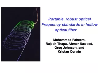
Portable, robust optical Frequency standards in hollow optical fiber. Mohammad Faheem, Rajesh Thapa, Ahmer Naweed, Greg Johnson, and Kristan Corwin. Motivation Develop high accuracy Portable Wavelength Standards for Telecommunication Industry . Outline. Introduction.

E N D
Portable, robust optical Frequency standards in hollow optical fiber Mohammad Faheem, Rajesh Thapa, Ahmer Naweed, Greg Johnson, and Kristan Corwin
Motivation Develop high accuracy Portable Wavelength Standards for Telecommunication Industry.
Outline Introduction Broadening Mechanisms and Saturation Spectroscopy Frequency measurement. Previous Work Our Approach Experimental Set-up Results Limitations Future Work
C2H2 Over View Laser 50 Torr ? Frequency measurement Frequency comb
Demultiplexer Fiber Coupler Sources Output Fibers Wavelength Division Multiplex Separation between channel is 1 nm - Channel adjustment in WDM (1525-1565 nm) system. - Calibration of wavelength measurement devices.
Recipe for a Wavelength Standard Atomic or molecular absorption lines -Absolute frequency reference. - Very stable under changing environmental conditions - Good references in the 1500 nm region Good references in 1500 nm region • Acetylene (1510-1540 nm) • Hydrogen cyanide (1530-1565 nm) • Rubidium (1560-1590 nm)
Acetylene ( Also called Ethyne) H C H C • - Colorless and extremely flammable • 50 transition lines, spaced by 60-80 GHz extending from • 1515nm-1540 nm C C H H CH n1 Symmetric C- H bond Stretching CC n2 n1+n3 lies in 1.5 mm region CH n3 Anti-symmetric C- H bond Stretching Stretching Vibrations
IO I Important Broadening In IR Spectroscopy • Absorption (Beer’s law) z ‘a ‘is the absorption cofficient Absorption sample • Power Broadening • Doppler Broadening C2H2 at room temp. ~ 500 MHz Laser spectroscopy by Wolfgang Demtroder
Important broadening near IR spectroscopy • Pressure broadening and shift Line Broadening C2H2 broadening P(10) ~ 11.6 MHz/Torr Line Shift C2H2line shift P(10) ~ 0.29 MHz/Torr • Transit-Time Broadening Transit timeT=d/v 500 KHz for 0.94 mm dia cavity Laser spectroscopy by Wolfgang Demtroder
Saturation Spectroscopy • Eliminates Doppler width • Requires high Power (Typically 300 mW for acetylene) • Dominant Line width • Pressure broadening (~11 MHz/Torr) • Transit-time broadening (coherence time between laser and molecules) • Power Broadening • Signal Size • Depends linearly on pressure • Depends linearly on sample length Laser 90% 10% B.S Pump Beam Probe Beam M2 M1 Cell Det.
Frequency Measurement Frequency = Cycles/second Definition of time Caesium 133 atom Duration of 9 192 631 770 period Of the radiation corresponding to the transition between two hyperfine Level of the ground state of Cs atom. Optical frequency ----- In hundreds of THz Its easy to measure in THz ? Photo Detector ------ In 40-100 GHz What we need to do? Mode Locking Frequency Comb
2Df E(t) Df t tr.t = 1/fr Time-Frequency Correspondence Fourier transform of periodic signal discrete frequency components. I(f) fo fr f fn = n fr + fo 0 fr Laser repetition rate fo Offset D. J. Jones, et al. Science 288, 635 (2000)
Measurement of fr and fo Repetition Rate fr can be measured with photo-detector in optical path Offset I(f) fo fr f f2n 0 fn 2fn-f2n = 2(nfrep+fo) - (2nfrep+fo) = f0 Octave Spanning - Microstructure fiber - Laser Cavity D. J. Jones, et al. Science 288, 635 (2000)
f A.Czajkowski,J.E Bernard,A.A.Madej,R.S.Winler Self reference frequency comb Unknown signal fr fo f Unknownsignal App.Phys.B79,45-20 (2004)
Spectrum Broadening 100 mW (1 nJ) 20 mW (0.2 nJ) Relative Power (db) laser spectrum Wavelength (nm) Solid core microstructure Fiber Fused silica core Cladding Core 1.7 m
Fiber in Fiber out Cr:forsterite Laser Fiber Laser SC BS 10 W 1075 nm HNLF stabilized optical frequency comb Synthesizer DM f Loop nonlinear rep Filter crystal Synthesizer f Loop Phase 0 Filter Detector Frequency comb Set-up
Previous work:K.Nakagawa, M.de Labachelerie, Y.Awaji and Kourogi (J.opt.soc.Am.B/Vol.13,No.12/December1996) Cavity : • Long interaction length. • High intracavity power (100 mw). • Fragile. • Cavity and laser locked to • resonance independently. Signal Measurement : • Two photon Rb (778 nm) transition as • a reference. • Hydrogen Cyanide(1556 nm, P(27)) as a • Intermediate reference.
Previous Work:W.C. Swann and S.L. Gilbert. (NIST) Pressure-induced shift and broadening of 1510–1540-nm acetylene wavelength calibration lines, ” Opt. Soc. Am. B, 17, 1263 (2000). Pressure broadening & shift For P(13) broadening 11.4 MHz/Torr Line shift 0.27 MHz/Torr Effect of Temp negligible effect Used to calibrate Optical Spectrum Analyzers (OSA’s)
Previous Work :A.Czajkowski, A.A.Madej, P.Dube Development and Study of a 1.5 um Optical frequency Standard referenced to p(16) Saturated absorption line in the (V1+v3) overtone band of 13C2H2 Optics Communications 234(2004) 259-268 Saturation signal ~ 1 MHz Measure Power shift 11.4 Hz/mw Pressure Shift 230 Hz/mTorr
Our Approach Develop high accuracy portable wavelength Standards for telecommunication industry. Through existing Technology : - Cavity based references are not Portable. - Transitions in the glass cells can not be further narrowed. Solution : Use molecular absorption inside optical fiber. Advantages: • Portable • Easy to align • Easier to get high intensities over long path.
To vacuum pump Capacitive manometers Gas Inlet Gas Inlet Hollow optical fiber Probe Pump 1 mW (15 - 300) mW C2H2 molecules Experimental Set-up ultimately: Fiber in Fiber out
C2H2Cell Setup- Optics PD Diode Laser Fringe width~156 MHz Mirror 50/50 d2 d1 Mirror BS PBS Pump Beam Probe Beam 10/90 Fiber EDFA 30/70 PBS PD ISO Probe Squeezer PBS PD ISO Pump Squeezer λ/2
Laser 2a Power loss Capillary Tube 1531.31 nm • Too lossy Length 18 cm and dia 330 µm • Only 40% transmission • Doppler Broadened signal observed • No saturation signal.
Capillary tube Satisfy Beer’s law 10 µm PBF gives 50 MHz saturation dip. 300 µm should give 1.73 MHz saturation dip. For saturation dip We need power 865 times
Photonic Bandgap fiber 10 mm loss< 0.02 dB/m No total internal reflection Bragg’s reflection
10-µm Photonic Bandgap fiber 1.2 Torr of 12C2H2 at 1531.31 nm Significant signal strength at 10 and 20 mW pump powers!
10-µm Photonic Bandgap fiber We are transit limited or pressure limited ? Line width does not increase significantly with pressure which implies that it is transit time limit.
20-µm Photonic Bandgap fiber 20 mm core, 60 cm length Fiber fills to 2 mTorr in ~ 10 s 20 µm, 83 cm long PBF at 1531.20 nm
20-µm Photonic Bandgap fiber Pressure limited ? Factor of 3 change in pressure gives a factor of 1.2 change in line width Transit limited
10-µm, 20- µm PBF data Comparison Transit Time To reduce Transit time Broadening: increase fiber hole size -or- find a heavier molecule -or- Decrease the velocity of molecule by cooling
Ultimate limits Signal strength: • optimal fiber length for pressure. Noise • Interference (probe with stray/reflected pump) • laser intensity noise Linewidth:(target < 1 MHz) • transit time broadening • pressure-broadening To narrow the transition, we must: • reduce transit-time broadening • reduce the pressure • lengthen the fiber
Conclusions - Observed saturated absorption features in photonic bandgap fiber for first time. - Significant absorption fraction observed at low power (< 20 mW), with 23 MHz-wide feature. - Confirmed transit time broadened, 20 mm produce narrower feature than 10 mm fibers
Future Plan • Near-term: • Make more portable, reduce noise. • Build frequency Comb for absolute measurement. • Observe dependence of different broadening mechanisms. • Observe the shifts in Photonic bandgap fibers. • Longer-term: • Seal the fiber filled with gas. (Greg Johnson) • Narrow the transition • Explore larger photonic bandgap fibers • Explore other gases.
Photonic Bandgap fibers Index guiding Hollow Core guiding
10 mm Saturated absorption feature width ~ 40 MHz Transit time broadening: Naive estimate t= d/v = ~1/50 MHz Pressure broadening: 11 MHz/Torr * 1.2 Torr = 13.2 MHz
Important Broadening In IR Spectroscopy • Doppler Broadening • Molecules are in motion when they absorb energy. This causes a change in • the frequency of the incoming radiation. • Pressure broadening • Produce by the shifts of energy levels by • interaction of radiating atom with near by • particles • Transit time Broadening • The interaction time of molecules with the • radiation field is small with the • spontaneous life time of excited levels • Power Broadening • Molecules absorb energy from intense laser. This causes a energy shift causing broadening.