Download
1 / 34
490 likes | 1.47k Views
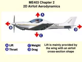
Chapter 2 Fundamentals of Rotor Aerodynamics. SONG, Jianyu . Warm up. Three functions of the rotor . Vertical lifting force in opposition to the weight Horizontal propulsive force for forward flight Control the attitude and position of the helicopter.

E N D
Chapter 2 Fundamentals of Rotor Aerodynamics SONG, Jianyu
Three functions of the rotor Vertical lifting force in opposition to the weight Horizontal propulsive force for forward flight Control the attitude and position of the helicopter separated 3 in 1 V.S.
Outline • Momentum theory Analysis in Hovering Flight • Momentum theory Analysis in Axial climb and Descent • Momentum theory Analysis in Forward Flight
Assumptions of the Flow • One dimensional • Flow properties across any plane paralled to the rotor paln are constant • Quasi-steady • Flow properties at a point do not change with time • Incompressible • The desitiy of the flow is constant • Inviscid • No viscous sheer between flouid element
Conservation Laws of Aerodynamics Conservation of fluid mass: Conservation of fluid momentum: Conservation of energy:
Application to a Hovering Rotor Fig 2.5: Different planes By conservation of mass By Conservation of momentum By Conservation of energy
By conservation of mass The ratio of the cross-sectional area of the far wake to the area of the rotor disk By considering the radius The ratio 0.707 is called the “wake contraction ratio”
Induced Velocity(Vi) and Rotor Power(P) By Conservation of momentum T/A is known as the “disk loading” The power required to hover: This power is called “ideal power” One can alternatively write: Cube of the induced velocity: large rotor disk area and less velocity for the minimum induced power
Pressure Variation Since there is a pressure jump, Bernoulli’s equation can not apply across the disk. Between station 0 and 1 Between station 2 and ∞ Assume the jump is uniform. Pressure jump equals to disk loading We can further determine the pressure in terms of disk loading just above the disk just below the dick
Disk Loading and Power Loading Disk loading(DL):T/A Power loading(PL):T/P PL decreases quickly with increasing DL. Thus rotors with low DL will require a low power per unit thrust (high ideal PL) and will tend to be more efficient Helicopter operate with low DL and is more efficient relative to other type of rotor aircrafts.
Induced Inflow Ratio • At the rotor disk, the induced velocity can be written as: • The nondimensional quantity is called the “induced inflow ratio in hover”. • For rotating-wing aircraft, it is the convention to nondimensionalize all velocities by the blade tip speed in hover.
Thrust and Power Coefficients Buckingham П method: N=5 variables K=3 fundamental dimensions N-K=2 or two П products The functional dependence can be written in the form will П1 and П2 are nondimensional groupings Thrust coefficient Inflow coefficient
Thrust and Power Coefficients Thrust coefficient: Relation of thrust coefficient and the and inflow ratio: Power coefficient: Relation with thrust coefficient: Torque coefficient: Numerically = Power coefficient Other definition:
Comparison of Theory with Measured Rotor Performance Fig2.7 the relation is essentially correct The differences between the momentum theory and experiment occur because viscous effects
Nonideal Effects on Rotor Performance Induced power κ: Induced power correction factor, it is empirical coefficient. Profile power (include drag force) (chapter 3) change to coefficient: σis “rotor solidity” (the ratio of blade area to rotor disk area) Fig.2.7 The result of the modified theory
Figure of Merit Efficiency factor for helicopter: PL:T/P is a dimensional quantity Figure of merit as a nondimensional measurement is adopted It can also be written as: Using modified theory: • It should only be used as a comparative measure between two rotors when the rotors are also compared at the same DL (i.e. T/A), since increase of DL will induce case FM increase
Axial Climb Conservation of mass: Conservation of momentum: Conservation of energy
Axial Climb For hovering: Conservation of momentum Solve the quadratic equation: Since in this situation, vi and vh in the same direction:
Axial Descent(Windmill State) Conservation of mass: Conservation of momentum: Conservation of energy
Axial Descent (Windmill State) For hovering: Conservation of momentum Solve the quadratic equation: One of the solutions let vi/vh>1, which violate the assumed flow model
Axial Descent(region between Hover and Windmill State) The measured rotor power can be written in the assumed form as: The region Since the flow can take on two possible directions and well-defined slipstream cases to exist This means that a control volume can not be defined that encompasses only the physical limits of the rotor disk. However, the velocity curve can still be defined empirically albeit only approximately, on the basis of flight tests or other experiments with rotors. Unfortunately descending flight accentuates interactions of the tip vortices with other blades and so the flow becomes rather unsteady and turbulent, and experimental measurements of rotor thrust and power are difficult to make. Also the average induced velocity can not be measured directly. Instead, it is obtained indirectly form the measured rotor power and thrust Using the result In addition to the measured rotor power:
Axial Descent(region between Hover and Windmill State) Many authors suggest a linear approximation to the measured curve. Young(1978) κ is the measured induced power factor in hover. A continuous approximation to the measured induced velocity curve at this rang is : k1=-1.125, k2=-1.372, k3=-1.718, k4=-0.655 • A better approximation to the measured curve is:
Power Required in Axial Climbing and Descending Flight In a climb or descent the power ratio is : 1st term is potential energy change 2nd term is work done on the air For climb: For quick descend:
Forward Flight The mass flow through the actuator is: in which: Conservation of momentum in a direction normal to the disk: Conservation of energy:
Forward Flight So For hovering flight: It confirms the equation=) As the forward speed increases : It is “high-speed” approximation.
Induced Velocity in Forward Flight In forward flight, the thrust is: Tip speed ratio( advance ratio): The inflow ratio:
Special Case α=0 The induced velocity ratio in forward flight is: The solution is: The result is show in Fig 2.24 The induced velocity decreases quite quickly with increasing forward flight velocity
Rotor Power Requirements in Forward Flight The rotor power in forward flight is given by: Reference to the hover result: Assuming staight-and-level flight: For vertical equilibrium: For vertical equilibrium The power equation in straight-and-level flight can be written as: The AoA of the disk relative to the oncoming flow will change in a climb or descent: In this casepower ratio can be written as: is climb velocity ratio.