Download
1 / 20
220 likes | 393 Views
Phylogeny (P) [Evolvability]. PO hw. PE hw. POE hw. Ontogeny (O) [Scalability]. OE hw. Epigenesis (E) [Adaptability]. Ontogenetic systems. Drawing inspiration from growth and healing processes of living organisms… …and applying them to electronic computing systems. Introduction.

E N D
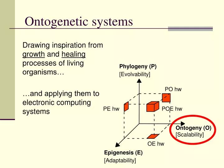
Phylogeny (P) [Evolvability] PO hw PE hw POE hw Ontogeny (O) [Scalability] OE hw Epigenesis (E) [Adaptability] Ontogenetic systems Drawing inspiration from growth and healing processes of living organisms… …and applying them to electronic computing systems
Introduction • Motivations for growth-based approaches : • Tackling complexity through scalability
Introduction • Motivations for growth-based approaches : • Tackling complexity through scalability • Several “theoretical” approaches: • L-Systems • “Blob” computing • Morphogenesis • Neuronal growth • Few practical approaches in electronics
Introduction • Motivations for growth-based approaches : • Tackling complexity through scalability • Fault tolerance through redundancy
Development in hardware • Mechanisms inspired by the biological process of growth (and healing) applied to networks of processing elements • The goal is NOT to mimic biology (or help biologists) but to solve problems in hardware design • The goal is NOT to grow form (morphogenesis), but function! i.e., design systems that use development to execute an application better/more efficiently/with non-standard constraints
Development in hardware – Why? • Let us assume that we want to implement a streaming application (i.e. an application that consists of a chain of discrete operations). For example an audio or video decoder. × IN ×+ ÷≠ FFT + DCT OUT
Development in hardware – Why? Option 1: software only OK, but (relatively) slow Option 2: hardware – full custom circuit Very fast, but expensive and inflexible (if the algorithm changes, the circuit must be redesigned) Option 3: hardware – dedicated processor Fast, but again if the algorithm changes, it needs to be redesigned together with the compiler, the programming tools, etc. Option 4: hardware – array of processing nodes …
Development in hardware – Why? Option 4.1: hardware – array of general-purpose processing nodes Fast, very much in fashion (multi-core, GPU), but very difficult to program and again not very flexible. Option 4.1: hardware – array of custom processing nodes Very fast, but difficult to implement and design × IN ×+ ×+ ÷≠ FFT + DCT OUT
Development in hardware – Why? • FPGAs (of various flavours) are the obvious solution to implement arrays of custom processors • But the design process is NOT simple
× ×+ ÷≠ FFT + DCT Development in hardware – Why? • Step 1: analyze the application and extract the component tasks × IN ×+ ÷≠ FFT + DCT OUT
× ×+ ÷≠ FFT + DCT Development in hardware – Why? • Step 2: as a function of the tasks, design one (or more) custom processors. × IN ×+ ÷≠ FFT + DCT OUT
× ×+ ÷≠ FFT + DCT Development in hardware – Why? • Step 3: program the FPGA to implement an array of processors. × IN ×+ ÷≠ FFT + DCT OUT
+ ×+ FFT DCT × ÷≠ × ×+ ÷≠ FFT + DCT IN OUT Development in hardware – Why? • Step 4: Assign the tasks to the processing nodes and set up the connection network. × IN ×+ ÷≠ FFT + DCT OUT
Option: array of custom processing nodes Step 1: analyze the application and extract the component tasks Step 2: design the custom processors Step 3: program the FPGA Step 4: assign the tasks to the processors and set up the connection network ← Multi-cellular organization ← Evolutionary process ← Totipotent / stem cells ← Growth (cellular division) ← Growth (cellular differentiation) Development in hardware – Why?
Growth Application self-organizes in a programmable substrate Programmable substrate × ×+ ÷≠ FFT + DCT Programmable substrate × IN ×+ ÷≠ FFT + DCT OUT
Environmental adaptation Self-organization is hard to justify for silicon! …unless growth and structural adaptation cannot be represented in a genome: they are influenced by environmental variables. • Substrate defects • Runtime faults • Performance parameters
Fault tolerance Programmable substrate • Faults at fabrication are increasing. • Self-organization is back! • Online faults are increasing • Self-organization is back! × × × ×+ ÷≠ + DCT FFT Similar mechanisms can be used for development and for self-repair (stem cells + differentiation!). Fault tolerance = environmental adaptation.
× FFT2 DCT ×+ ÷≠ FFT + DCT Environmental adaptation • Application self-organizes depending on input stream – structural adaptation IN OUT × FFT2 DCT ×+ ÷≠ FFT FFT + DCT DCT
Next lectures • Lecture 2 – Week 4 (Nov. 1): • Cellular automata and self-replication • Lecture 3 – Week 4 (Nov. 4): • Self-replicating loops and the Tom Thumb algorithm • Lecture 4 – Week 5 (Nov. 7): • Embryonics • Lecture 5 – Week 6 (Nov. 18): • Self-replicating electronic circuits • Lecture 6 – Week 8 (Nov. 29): • Adaptive processor arrays • Lecture 7 – Week 8 (Dec. 2): • Adaptive processor arrays - continued • Lecture 8 – Week 9 (Dec. 6): • BioWall demo