Download

1 / 36
370 likes | 712 Views
Robotic Arm and Dexterous Hand. Critical Design Review February 18, 2005. The Team. David Parrett. Wen Jia Wang. Jeremy Amidon. Justin Tubiolo. Ken Peters. Overview. Needs and Objectives Requirements and Specifications Design Analysis and Synthesis User Input Device

E N D
Robotic Arm and Dexterous Hand Critical Design Review February 18, 2005
The Team David Parrett Wen Jia Wang Jeremy Amidon Justin Tubiolo Ken Peters
Overview • Needs and Objectives • Requirements and Specifications • Design Analysis and Synthesis • User Input Device • Mechanical Operation • Mechanical Power • PC and Microcontroller Programs • Electrical Output Circuit • Feasibility Assessment • Future Plans • Schedule and Budget
Project Needs & Objectives • Maximum exhibit life span and durability. • Intuitive navigation and operation by users. • Robotics theme an exceptionally inviting "attractor factor." • Accessibility to many users of different age and physical ability. • Provide maintenance information and details. • The robotics exhibit becomes an extension of the human arm. • Test the display in its target environment to ensure success.
Project Specifications • The Input Device detects four movements of the hand and the fingers • The Robotic Arm moves with 4 large muscles • The wrist operates as a hinge, moving the hand up and down approx. 45o • The elbow operates as a hinge, moving the hand and arm up and down approx. 45o • The shoulder rotates the entire arm around approx 180o • The upper arm lengthens and contracts a distance of at least 1 foot (0.3 m) • The Robotic Hand contains five fingers, 4 of which can move separately • The thumb, index, and pinky fingers are able to move separately • The middle and ring fingers move together • The fingertips contract from open position to 90o partly closed
Design Analysis • User Input Device • Mechanical Operation • Mechanical Power • PC and Microcontroller Program • Electrical Output Circuit
Concept Block Diagram Glove Controller Air Pressure Supply Personal Computer Limiting Sensor Microcontroller Air Valves Table Touch Sensor Air Muscle Movement Cables Elbow Joint Extension Cylinder Finger Joints Rotational Motor Wrist Joint
User Input Device • Sensor Laced Glove & Fighter Joystick • Utilize Flex Sensors in the Glove • Sensor Glove with Motion Track • Glove has Flex Sensors in the Fingers • Infrared Receptor Senses Motion in 6 Degrees Courtesy of http://devices.sapp.org/component/flex/
P5 Data Glove Courtesy of Essential Reality
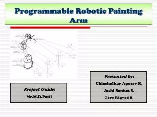
Arm Concept • Arm With Wrist, Elbow & Rotating Cylinder • 4 Degrees of Freedom • Maximum Reach
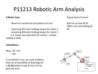
Power Source Concepts • Electric 24 Volt DC Motors • For the cylinder a high speed and high current DC Servo Motor is used • For the rotation of the arm a motor with a gearbox is used for higher torque and slower speed
Power Source Concepts • Pneumatics • Utilize air muscles • Power-to-Weight Ratio up to 400:1 • Apply Forces up to 140 lbs. • Very Flexible Photo courtesy of Shadow Robot Company
Pneumatics • Air muscles are controlled by 24 volt solenoid valves
Valve Lifespan • Valves are rated for 200 million cycles
Finger Curl Problem • Linear motion of muscles was inadequate
Electrical Input/Output • Inputs to PC • USB signal from glove controller • Output from PC • RS-232 serial output to MDB • Inputs to MDB • Serial input to the UART from the PC • Magnetic field sensors from arm cylinder and rotating gear • Touch sensor to detect when the hand touches the display table • Output from MDB • Digital signal to each valve to control pressure in air muscle • Extension cylinder motor control lines
Serial port • 9 PIN RS-232 serial port is used to send motion control data to the microprocessor
Serial Port Encoding Each clock cycle the serial port transfers 8 bits of data:
Control Concept • Arm Motion Control • When the glove is moving, then the arm moves in the same direction controlled by these signals from the glove: • ‘x’ Axis controls rotional motor • ‘y’ Axis controls elbow motion • ‘z’ Axis controls extension cylinder • ‘pitch’ Axis controls the wrist motion • Finger Motion Control • Motion control theory for the fingers is same as for the arm • Each robotic finger is controlled by each finger sensor on the glove
PC Program • Initialize the P5 Glove • Initialize the Serial Port • Begin Main Loop • Update Glove Variables with current data • Filter Incoming Data to detect motion above a certain threshold • Convert Filtered Data to an 8-bit serial output • Send output byte to the serial port • Loop forever
Microprocessor Program • Setup the UART for serial transmission with interrupts • Setup the ports for correct I/O • Begin Main Loop • Look at the most recent incoming serial data • Check the first 3 bits for motion ID • Check the last 2 bits for desired motion • If the sensor feedback allows this motion, execute this motion and send output to port • Loop forever
Control Circuit Fan resister Out put from BJT (3V) Air muscle valves Control relays Power switches Input from microprocessor Motor control relays Connect to motor Connect to Motor (24V)
Low Signal Relay • Max. operating voltage 125 VAC, 60 VDC carry current 1 A • Rated voltage (VDC) 3 • Rated current (mA) 33.0 • Coil resistance (Ω) 91
BJT AMP board Input from microprocessor (3.3V 25mA) Output to relays (3v 50mA)
Power supply • Voltage output of 24 V • Maximum current of 2.5 A • Over voltage protection • Over current protection
Final Circuits Output to air valves and motors BJT board Control circuit Power Supply (24V 5A) Microprocessor