Download
1 / 12
120 likes | 241 Views
PERTURBATION MEASUREMENTS ON OVERHEAD NETWORKS USING ELECTRIC FIELD SENSORS. ISSOURIBEHERE – Argentina – RIF Session 2 – 0513. Where: u(t) = Potential to be determined [V]. u m (t) = Potential measured with the EFS [V].

E N D
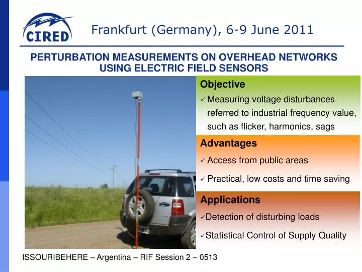
PERTURBATION MEASUREMENTS ON OVERHEAD NETWORKS USING ELECTRIC FIELD SENSORS ISSOURIBEHERE – Argentina – RIF Session 2 – 0513
Where: u(t) = Potential to be determined [V]. um(t) = Potential measured with the EFS [V]. GV = Voltage gain between the output of the electric field sensor and the measurement equipment [V/V]. kE = EFS transduction constant = [m]. kG = Geometric constant of physical installation [1/m]. PERTURBATION MEASUREMENTS ON OVERHEAD NETWORKS USING ELECTRIC FIELD SENSORS Measuring an electric field between two electrodes. It is similar to a capacitive voltage divider where the HV capacitor has been replaced by a parasitic one. Principle used in HV Labs For measuring perturbations - referred to the fundamental frequency voltage – It is only necessary to reproduce the waveshape. Due to this it is not necessary to know the constants GV, kE, kG, being enough to verify the linearity and the independence of the frequency. ISSOURIBEHERE – Argentina – RIF Session 2 – 0513 2
b c a PERTURBATION MEASUREMENTS ON OVERHEAD NETWORKS USING ELECTRIC FIELD SENSORS Solving equations, the mathematic result is: Testing the circuit, the result is: One channel EFS measurement reproduces + and – sequence but not 0 ISSOURIBEHERE – Argentina – RIF Session 2 – 0513 3
PERTURBATION MEASUREMENTS ON OVERHEAD NETWORKS USING ELECTRIC FIELD SENSORS ISSOURIBEHERE – Argentina – RIF Session 2 – 0513 4
Frequency Response. The transducer is installed inside a parallel plate capacitor. LV tracking generator PERTURBATION MEASUREMENTS ON OVERHEAD NETWORKS USING ELECTRIC FIELD SENSORS HV Lab experiences and contrast Flicker and harmonics were applied to a HV installation using a LV/HV transformer excited with an electronic power generator. IEC meters were used Measurement system EFS + recording equipment meet error 5 %, IEC 61000-4-15 Flicker standard and Class I IEC 61000-4-7 Harmonics standard. ISSOURIBEHERE – Argentina – RIF Session 2 – 0513 5
PERTURBATION MEASUREMENTS ON OVERHEAD NETWORKS USING ELECTRIC FIELD SENSORS Field measurements Flicker comparison: HV with EFSvsLV conventional Subtransmission area explored Flicker in Bragado LV conventional measurements Flicker HV with EFS vsLV conventional ISSOURIBEHERE – Argentina – RIF Session 2 – 0513 6
PERTURBATION MEASUREMENTS ON OVERHEAD NETWORKS USING ELECTRIC FIELD SENSORS Field measurements Localizing flicker Sources ISSOURIBEHERE – Argentina – RIF Session 2 – 0513 7
PERTURBATION MEASUREMENTS ON OVERHEAD NETWORKS USING ELECTRIC FIELD SENSORS Localizing flicker Sources Summary • 1.Flicker measurements in overhead lines with the EFS are feasible to perform in compliance with required uncertainties, according to International Standards. • 2. The following steps shall be carried out to find the geographic location of the prevailing Flicker source: • Perform measurements with an EFS in different nodes of the power system – keeping one conventional Flicker measurement in a reference place –. • Obtain the topology and the electrical data of the power system to be inspected, and determine (by manual calculations or by computer simulations) the effects of a predominant Flicker source in different nodes of the power system. • Correlate both results and determine the geographic location of the predominant Flicker source. ISSOURIBEHERE – Argentina – RIF Session 2 – 0513 8
PERTURBATION MEASUREMENTS ON OVERHEAD NETWORKS USING ELECTRIC FIELD SENSORS Harmonic measurements Results obtained with the same EFS, during flicker measurements Saladillo node was over the 5th harmonic limit Chacabuco node should be checked longer The other nodes are within the limits The results for the 3rd harmonic and its multiples should be considered only as indicative ISSOURIBEHERE – Argentina – RIF Session 2 – 0513 9
PERTURBATION MEASUREMENTS ON OVERHEAD NETWORKS USING ELECTRIC FIELD SENSORS Remarks • It is a practical way to measure harmonics, flicker and other perturbations related to industrial frequency voltage, in compliance with IEC rules under 1Φ/3Φ grids (+,- seq, not 0) • It can be used as a powerful tool for finding disturbing loads along aerial transmission / distribution grids by accessing from public areas • It is a useful tool for statistical inspection of PQ in widespread electrical systems • The EFS based measurement method is particularly useful where both cost and physical location drawbacks cannot be addressed ISSOURIBEHERE – Argentina – RIF Session 2 – 0513 10
PERTURBATION MEASUREMENTS ON OVERHEAD NETWORKS USING ELECTRIC FIELD SENSORS References [1] M.Del Pozo, D.Esteban, P.Issouribehere, G.Barbera (IITREE FI-UNLP) A. Funes, A. Ledezma (YACYLEC), 2010, "Field measurements and modelling of high frequency transients during disconnect switch operations in EHV Substations. Assessment of their effects on Current Transformers", International Congress of CIGRE (Conseil International des Grands Réseaux Electriques). Paper: A3_207_2010. Paris, France, Ag. 2010. [2] G. Casas, P. Issouribehere “Aplicación de un medidor de campo eléctrico como transductor para mediciones de perturbaciones en redes”. II ERLAC CIGRE CE 36. Puerto Iguazú, Argentina, junio 1987. [3] ENRE (Argentina) Resoluciones 184/00: “Base Metodológica para el Control de la Calidad del Producto Técnico. Etapa 2” y ENRE 99/97: “Base Metodológica para el Control de la Emisión de Perturbaciones. Producto Técnico - Etapa 2” [……….] IEC EMC Standards ISSOURIBEHERE – Argentina – RIF Session 2 – 0513 11
PERTURBATION MEASUREMENTS ON OVERHEAD NETWORKS USING ELECTRIC FIELD SENSORS Daniel Esteban, Fernando Issouribehere, Pedro Issouribehere Instituto de Investigaciones Tecnológicas para Redes y Equipos Eléctricos IITREE-LAT)FACULTAD DE INGENIERÍA - UNIVERSIDAD NACIONAL DE LA PLATA - ARGENTINA www.iitree-unlp.org.ar ISSOURIBEHERE – Argentina – RIF Session 2 – 0513 12