Download
1 / 14
580 likes | 2.23k Views
Design of a Disc Brake. Tania M. Ortiz Menéndez Liza M. Cardona Gonzalez Ramon Torres. Objectives. Design of the rotor component for a disc brake system using load analysis, stress analysis and fracture analysis system approach. . Description.

E N D
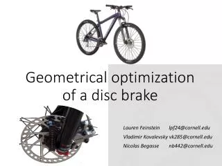
Design of a Disc Brake Tania M. Ortiz Menéndez Liza M. Cardona Gonzalez Ramon Torres
Objectives Design of the rotor component for a disc brake system using load analysis, stress analysis and fracture analysis system approach.
Description • Single disc brake component from a brake system compound of a master cylinder, a four piston caliper, two brake pads and the rotor. • It is supposed to produce a torsion from an input driver force of 100 lb.
Mechanical Design • Pedal force = 600 lb • Master Cylinder = 1559.4 psi • Caliper Force = 78367.3 lb • Pads Force = 35265.3 lb • Rotor Torque = 437289.8 τ = 409.97 psi
Material Selection • Gray Cast Iron: wear resistant, hard, good heat absorption and dissipation. • Sut = 40000 psi • Suc = 150000 psi
Mechanical design • Kt = 2.5 (assumed) • τ(corrected) = 1024.9 psi Static Fracture Analysis (Internal Friction Theory) • σ 1 = 1024.9 psi, σ3 = -1024.9 psi • n = 30.81
Mechanical Design Dynamic Fracture Analysis • Se’ = 16000 psi • Ksurf = 1.016 • Ksize = 0.7296 • Kload = 0.59 • Ktemp = 1 • Krel (99.9%)=0.814 • Se = 5695 psi
Mechanical Design • q = 0.8 (assumed) • Kf = 2.2 • Ta = 437289.8 lb • τa(corr) = 901.934 psi • σ1 = 901.94 psi, σ3 = -901.93 psi • Tm = 218644.9 lb • τm(corr) = 450.98 psi • σ1 = 450.98 psi, σ3 = -450.98
Mechanical Design • Modified-Goodman nf = 5.896
Mechanical Design • Tm = 218644.9 lb • τm(corr) = 450.98 psi • σ1 = 450.98 psi, σ3 = -450.98 psi • nf = 5.896 (Goddman) Endurance Limit • N = 99.2 x 10⁷
Conclusion • With this project we achieved a safe, durable and viable design for a rotor component in a disc brake system taking in consideration the forces exerted for all the components in the brake system. In our fracture analysis for the static and the dynamic approach we found that our safety factor numbers are elevated. With this we demonstrate that disc brakes do not fracture. That is because the force exerted in the disc is a compressive force. That’s why the materials used for the manufacturing of brake disc are brittle. Also for that reason we calculate a big endurance limit.