Download
1 / 55
550 likes | 774 Views
PEER TO PEER GROUP FORMATION AND COLLABORATION IN A REMOTE LABORATORY. Program Committee : By : Prof. Kanchana Kanchanasut Prithula Dhungel Dr. Yasuo Tsuchimoto Department of Computer Dr. Paul Janecek Science and Information Management School of Engineering and Technology

E N D
PEER TO PEER GROUP FORMATION AND COLLABORATION IN A REMOTE LABORATORY Program Committee : By : Prof. Kanchana Kanchanasut Prithula Dhungel Dr. Yasuo Tsuchimoto Department of Computer Dr. Paul Janecek Science and Information Management School of Engineering and Technology Asian Institute of Technology 20th April 2006, SOI Asia/AI3 joint Meeting 2006, Spring18-20 April 2006, Hua Hin, Thailand
Outline • Background • Problem Definition • Objectives • Methodology • Design • Implementation • System Evaluation • Conclusion
Consider a scenario in a University Given Scenario Many laboratories inside the university desiring to provide remote laboratory access to remote users In each of the laboratories, experiment equipment interfaced to a computer Control System Microprocessor Thermodynamics
Remote Student Remote Student Scenario …. Remote Student Different students interested in performing different laboratory experiments inside university (a single university)
Remote Student Remote Student Remote Student Scenario …. • For each laboratory, they want to perform experiments in • group and collaboratively control remote equipment
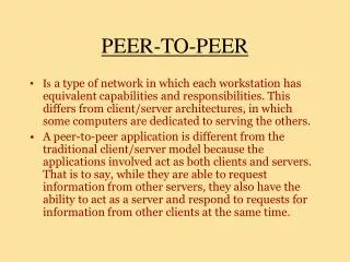
Scenario …. • Direct communication with each other and node providing device resources, without going through any central entity = > Peer to Peer environment • Role based access right to control the experiment equipment (teacher, student) • Teacher = > more privileges • Student => less privileges
Remote Student Remote Student Remote Teacher Scenario …. Inside Each Group Student Teacher Student
Requirements • Provide remote collaborative access to all laboratories in the University • Such a way that multiple laboratories in University are integrated into a single system
Server Remote Laboratory – The Past [1] No concept of group formation and collaboration Remote Student Figure : NUS Remote Laboratory System
Remote Teacher Remote Student Remote Student Remote Laboratory – The Past [2] • Allows group formation and collaboration among users • Allows various roles to group members (teacher and student) Server Remote Equipment Figure : Web-based Environment for Collaborative Remote Experimentation(University of Hagen)
Problem • Different laboratories inside a single University not integrated into a single software system • Users desiring to connect to different systems one by one should connect to each system separately (possibly using different user interfaces)
Steps to Fulfill Requirements • Form multiple simultaneous groups of people based on their interest (people with same interest brought together in same group) 2) Provide access right assignment based on roles (teacher, student ) to members in each group 3)Allow collaborative conduction of experiment in each experiment group controlling actual hardware equipment 4) Allow member exit from group without effecting the working of the system
Steps to Fulfill Requirements • Step 3 requires design and implementation specific to hardware devices in each laboratory • Outside scope according to time and device constraints
Hence .. The Objectives 1) Design architecture to form multiple simultaneous groups of nodes based on interests (integrate laboratories inside University to single system) 2) Design an architecture to provide role bases access right assignment to members in each group 3) Provide collaboration among members (text messages) 4) Allow members to exit from respective groups • Implement the designed system 6) Evaluate system performance using performance metric like delay, traffic flow, scalability, etc.
Design : Group Formation • Peer to Peer Technology in ApplicationLayer • An overlay (logical ) network in Application layer • Each peer has knowledge of the identities of only a certain number of peers in the network (neighbors) overlay edge (logical connection)
Peer to Peer Network – What? • Nodes wanting to participate in laboratory experiments enter laboratory network as peers: nodes hosting equipment and students (and teachers) wanting to perform experiment • Peers enter into Peer to Peer Network and announce their interests tosearch for other peers that share the same interest with them, using the help of neighbors
Group Formation– Pastry [3] • Nodes arranged in a logical circle • Concept of Nodes and Group Names • Node : Node wanting to be part of one of the groups • Group Name : Name of the laboratory experiment • group (Control System, Thermodynamics, • Microprocessor) • Node ----- > UNIQUE identifier (Hash IP, 128 –bit) • Group Name ------ >UNIQUE key (Hash Group • Name, 128 – bit)
Group Formation …. • A Group Namewith key K is mapped to a certain node in nodeID space (node that has nodeID numerically closest to the value of key K) • Suppose, Key(Control System) = K Node responsible for key K Node X • Key KNode X Rendezvous Point for Key K MAPPED TO Responsible for storing information about group named Control System (key K)
Group Formation – How ? Send message tagged with key K • Any message, sent by any node in network, tagged with key K will be routed to Node X(i.e. to node that has nodeID numerically closest to key K) Key(Control System) = K Message, Key = K Node X, responsible for key K Rendezvous Point for the group Control System
Group Formation – How ? Node Interested in Microprocessor Node Interested in Thermodynamics Node Interested in Control System Microprocessor RP Group List Register Group List Group List Group List Register Register Register Thermodynamics RP Control System RP
Design : Role Based Access Right Assignment • Our Scenario: • One or more hardware devices connected to each other and all interfaced to a single node (Resource Provider) • Performing experiment : changing parameters of one or more devices, that changes the output of the device and entire experiment
Role Based Access Right Assignment …. • Each node plays one of the following roles : • Resource Provider : one per group (Analogous to the file system for Unix) • Teacher: one per group (Analogous to the super user for Unix) • Student: one or more per group (Analogous to the normal user for Unix) • Access Rights : • Control (Send control signals to a device) • Changing the parameters of the device • 1 controller per device possible • Observe(Observe the output of a device) • Numerous observers per device possible
Device List Request CHANGES in Controller/Observer details for each device Access Right Request (Control, Observe, Revoke) ABC XYZ CHANGES in Controller/Observerdetails for each device CHANGES in Controller and Observerdetails for the device Controller and Observerdetails for each device Check Request validity Resource Provider Access Right Assignment
Design : Collaboration Among Members • Each group formed is a mesh • Each member knows of all other existing members of the group • Collaboration (text messages) is direct among members without going through any central entity • Collaboration • One to one • One to many
BYE BYE BYE ABC XYZ Design : Exit from Group Inform existing group members Resource Provider Exit from Group
Exit from Group …. Inform RP Send BYE message tagged with key K Key(Control System) = K BYE Message, Key = K Rendezvous Point for the group Control System
Implementation • FreePastry 1.4.2 API [4] using Java in Application Layer • Xcast6 API [5] for using Xcast in the Network Layer (using C) (Bandwidth saving) Free Pastry 1.4.2 XCAST6 • Used JNI (Java Native Interface) to call C • functions from Java • FreeBSD platform
System Evaluation : Criteria • Traffic Flow • Compare performance of our system with other system using Unicast • Stress on RP, stress on exiting node, stress on Resource Peer • Total traffic flow in network for Group Formation, Group Leave, Access Right Update • Scalability • Ability of system to perform well in presence of large number of nodes • Maximum members in each group, maximum simultaneous groups
System Evaluation - Scenario • Traffic Flow • Analytically for 3 Topology Scenarios
Scenario : Traffic Comparison Topology 2 Topology 1 Topology 3
Result : Traffic (Stress) Stress – Traffic flow in RP when new node arrives Explanation - Sender has to send 1 packet instead of n individual packets to n receivers
Result : Traffic (Network) Group Formation Traffic – Traffic that flows in whole network when a new node arrives to a group Explanation - Traffic gain in sender side is overwhelmed by the price receivers have to pay in terms of increased header size of XCAST - Data being transmitted is less in size
Result : Traffic (Network) Explanation - Traffic gain in sender side is more in comparison to price receivers have to pay in terms of increased header size of XCAST - Data being transmitted is large enough in size
Result : Scalability • Maximum Number of Members in a Group Figure : Limit in the Group Size due to New Member Notification Message Explanation - XCAST6 does not support packet fragmentation - XCAST6 packet size limited to MTU of 1500 bytes
Result : Scalability • Maximum number of simultaneous groups • Depends on the scalability of Pastry ring in terms of maximum number of groups • Balanced Load property [6] of uniform hashing technique used in Pastry ensures even distribution of keys among all nodes • No one node is overloaded by having to be RP for unreasonably high number of group names • Each member can register for one group at a time • If n members present in ring, maximum possible number of registrations for separate groups in the ring is n => n simultaneous groups can exist • Theoretically maximum 2 128 nodes possible in ring • Theoretically, maximum 2 128 simultaneous groups possible
Conclusion • Addressed the problem of integrating numerous laboratories into single system • Designed and implemented P2P based architecture to form multiple simultaneous groups (theoretically 2 128 groups possible); role based access right assignment inside each group • Our design is efficient : failure of any one node does not affect the process of group formation and collaboration in entire network. • Use of XCAST6 technology decreases the stress on sender side but increases the traffic flow in whole network • System proposed will be able efficient in terms of traffic flow when later phases of remote laboratory will be implemented • Results obtained in terms of maximum number of members and devices in each group are well above the requirement for practical collaborative remote laboratory groups
Future Work • Provide user authentication and security • Implement the design proposed to provide robustness in presence of silent departure of nodes from the system • Design and implement each laboratory specific system in the Resource Peer for interfacing and controlling respective experiment equipment • Provide key word based searching for groups such that it obviates the need for any member to know the exact group name
References 1) Ko, C.C. et al. (2001). A Webcast Virtual Laboratory on a Frequency Modulation Experiment. IEEE Conference on Decision and Control, Orlando, FL. • Röhrig, C., & Bischoff, A. (2003). Web-based Environment for Collaborative Remote Experimentation.Proceedings of the 42nd IEEE Conference on Decision and Control Maui, Hawaii USA. • Rowstron, A., & Druschel, P. (2001). Pastry: Scalable, Decentralized Object Location and Routing for Large-Scale Peer-to-Peer Systems. In the proceedings of the 18th IFIP/ACM International Conference on Distributed Systems Platforms, Heidelberg, Germany. • FreePastry (2005). The FreePastry homepage. Retrieved November 2005, from: http://freepastry.org/FreePastry/ • XCAST over IPv6. Retrieved November 2005, from the SourceForge website: http://sourceforge.net/projects/xcast6/ • Karger, D. et al. (1997). Consistent Hashing and Random Trees: Distributed Caching Protocols for Relieving Hot Spots on the World Wide Web. STOC 97, EI Paso, Texas, USA.
THANK YOU (QUESTIONS ?)
Pastry • Based on the concept of Distributed Hash Tables (DHTs) • Hash Table • Given a key, finds the location in the table where the key belongs • DHT • The tables are distributed • Given a key, finds the node where the key belongs
DHT for P2P Systems • Organize DHTs as nodes in an overlay • Every node in DHT knows about few other nodes in DHT • Every node has a unique ID • When node receives query for key K: • Forwards the query to neighbor whose ID is closest to K
Circular DHT • Each node has two neighbors: successor and predecessor • Information of a key is stored in closest successor
Who’s resp For key 1110 I am Circular DHT 0001 O(N) messages on avg to resolve query 1111 0011 information related to key 1110 stored here 0100 1100 0101 1010 1000
Pastry • Each node is assigned a 128-bit nodeID • The nodeID is viewed in base 16 • e.g., 65a1fc04 • nodeID indicates node’s position in a circular nodeID space • Each node knows its predecessor and successor nodes as well as few other nodes • Node forwards message to node whose nodeID shares with K a prefix that is at least one digit longer than that the key shares with the present node’s nodeID
Pastry …. • Each node maintains a leaf set and a routing table • LeafSet • Contains nodeIDs and IP Addresses of L closest nodes (closest in terms of nodeId value) • Routing Table • ith entry of table contains nodeIDs and IP Addresses of nodes sharing i prefixes with the nodeID of the node (O(log N)) • Given a message tagged with key K, Pastry scheme routes the message to node that has a nodeID closest to K in value (O(log N) steps
Pastry Routing Table Row 0 Row 1 Row 2 Row 3 log16 N rows
Pastry Routing Procedure if (destination is within range of our leaf set) forward to numerically closest member in leaf set else if (there’s a longer prefix match in routing table) forward to node with longest match else forward to node in table (a) shares at least as long a prefix (b) is numerically closer than this node
Pastry …. • New node join • Suppose new node with ID X joins the network • Should know the IP Address of at least one node already in the ring => BootStrap node • New node sends join message to the ring (via the BootStrap node) with a key X • Join message will be routed to node Z (say) that is currently responsible for key X • LeafSet of Z is the LeafSet for X • Routing Table for X: • All nodes encountered by join message on the way to nodeZ, send one row of their routing tables to X • ith node encountered sends ith row
Multi unicast n packets for n receivers R4 B R1 R2 R3 R8 A C R5 R6 R7 R9 D Figure : Multi unicast Multi unicast wastes bandwidth since a packet per receiver is to be generated and transmitted (for n receivers, n packets from the source)
Multicast 1 packet R4 B R1 R2 R3 R8 A C R5 R6 R7 R9 Figure : Multicast D • Only 1 packet coming out from the sender, but • Overheads : • Multicast routing entry per group in all intermediate routers • Multicast routing protocols required