Download
1 / 20
210 likes | 322 Views
Spar Mill Work-Holder. University of Idaho 2008 Capstone Project Sponsored By Boeing. Sparmill Team: Members: Ryan Mathews, Andy Florence, Ben Puyleart . Instructor: Jay McCormack Mentors : Chris Huck, Russ Porter. Problem Definition. Background:

E N D
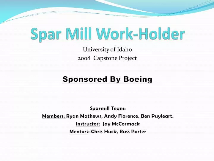
Spar Mill Work-Holder University of Idaho 2008 Capstone Project Sponsored By Boeing • Sparmill Team: • Members: Ryan Mathews, Andy Florence, Ben Puyleart. • Instructor: Jay McCormack • Mentors: Chris Huck, Russ Porter
Problem Definition • Background: • Boeing’s Auburn Plant manufactures airplane wing spars which are the primary structural component that runs the length of the wing. • The spar mill work holder secures the aluminum work piece while the mill shapes the components, which can be over 150 feet in length. • Currently, the work piece is hydraulically clamped down onto the work holder. • The current spar mill work-holder in place at the Boeing Company’s Auburn Skin and Spar Division has been causing a maintenance problem for the last 15 plus years due to hydraulic failures. Problem: The product opportunity is to reduce the occurrence of failure in the current work-holder while maintaining clamping specifications.
Final Design Key Features: Common Shaft: Rigidly connects two clamps to reduce the quantity of hydraulic cylinders Spring System: Springs supply 1500 [lb] clamping force rather than the hydraulic cylinders Release Arm: Allows for release of the spar. Prevents side loading of the hydraulic cylinder.
DFMEA-(Design Failure Mode Effects Analysis) • One example with recommended actions
Spring Testing Spring rate: 430 [lbf/in] No hysteresis effect
Force Testing Hydraulic pressure: 520 [psi] Cylinder Force: 2144 [lbf] Clamping Force: 1244 [lbf] Friction Effects: causing lower clamping force Frictional Torque: 2102 [lbf*in] Clamping Force Torque: 9165 [lbf*in] Spring Torque: 11267 [lbf*in]
Retrofitting Cost Estimate(Per 2 Foot Section) • Rocker Arm and Shaft Assembly $510.00 • Pushrods $24.00 • Springs (2 each) $115.00 • Hardware (bolts/pins/chain) $40.00 • Spring Housing $80.00 • Labor $250.00 • Total $1019.00 • (Costs in bulk would likely be considerably less)
Future Work/ Recommendations • Shielding of the spring and cylinder. • Possible heat treating of common shaft and keyways. • Improve ease of cylinder changeout (quick release fittings). • Alter design for quick and inexpensive retrofitting of current base. • Develop automatic safety lockout system.