Download
1 / 10
210 likes | 790 Views
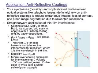
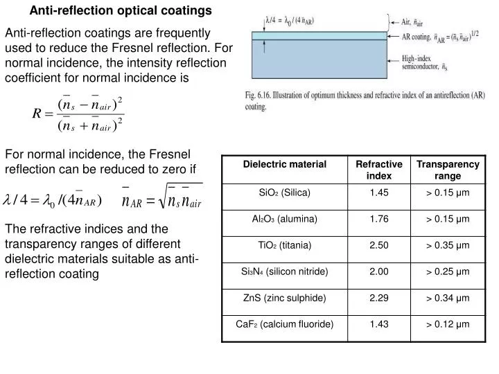
Anti-reflection optical coatings Anti-reflection coatings are frequently used to reduce the Fresnel reflection. For normal incidence, the intensity reflection coefficient for normal incidence is. For normal incidence, the Fresnel reflection can be reduced to zero if.

E N D
Anti-reflection optical coatings Anti-reflection coatings are frequently used to reduce the Fresnel reflection. For normal incidence, the intensity reflection coefficient for normal incidence is For normal incidence, the Fresnel reflection can be reduced to zero if The refractive indices and the transparency ranges of different dielectric materials suitable as anti-reflection coating
Epoxy dome Encapsulation occurs when the epoxy is in liquid state. Epoxy reduces the refractive index contrast between the semiconductor and air. The refractive index of epoxy is 1.5 A lower index increases the angle of total internal reflection thereby enlarging the LED escape cone and extraction efficiency. Epoxy usually has the shape of a hemisphere so that the angle of incidence at the epoxy-air interface is always normal to the epoxy surface, the total reflection does not occur at the epoxy-air interface. Planar-surface LEDs are frequently used where the intended viewing angle is close to the normal incidence or where the LED is intended to blend in with a planar surface. Epoxy domes provides protection against unwanted mechanical shock and chemicals, stabilizes the LED die and binding wire, provides the stability to the two metal LEDs and holds them in place, remains transparent for the longer emission wave lengths and does not show any degradation over a period of many years. But degrades and loses transparency in LEDs emitting at shorter wavelengths.
Distributed Bragg reflectors 50% of the light emitted by the active region is absorbed by the substrate. Absorption of light can be avoided by placing a reflector between the substrate and the LED active layers. Light emanating from the active region towards the substrate will then be reflected and can escape from the semiconductor through the top surface. DBR-multilayer reflector consisting of typically 5-50 pairs of two materials with different refractive indices. Difference in refractive index the Fresnel reflection will occur at each of the interfaces. Thickness of the two materials is chosen so that all reflected waves are in constructive interference. For normal incidence this condition is fulfilled when both material have a thickness of a quarter wavelength of the reflected light:
For an oblique angle of incidence Θl,h the optimum thickness for high reflectivity are given by • DBR must fulfil several conditions: • Since DH is grown on top of the DBR, the DBR must be lattice matched to the DH to avoid misfit dislocations. • To attain high reflectivity DBRs, the DBR needs to be transparent at the wavelength of operation unless the DBR has a high-index contrast. High index contrast DBRs yield high reflectivity. • If the DBR is in the current path, the DBR must be conductive. • Reflectivity of high-contrast DBRs is much higher than the reflectivity of low index contrast DBRs . • The width of the stop band of the high index difference DBR is much wider than the stop band width of the low-contrast DBR.
Period of the DBR Ll + Lh . Reflectivity of a single interface: Reflectivity has a maximum at the Bragg wavelength. The reflectivity at the Bragg wavelength of a DBR with m quarter wave pairs The stop band of a DBR depends on the difference in refractive index of the two materials Spectral width of the stop band will be given by effective refractive index of DBR
Finite number out of the total number of quarter-wave pairs are effectively reflecting the wave. The effective number of pairs For thick DBRs (m →infinity), the tanh function approaches unity Reflectivity of the DBR depends on the polar angle of incidence and on the wavelength. Reflected intensity can be obtained by integration over all angles. The reflectance at a certain wavelength λ is then given by Total light intensity reflected by the DBR is given by Ii(λ)-emission intensity spectrum of the active region incident on DBR. Ir-Intensity reflected by the DBR.
Ideally the layers comprising the DBR are transparent, which have negligible absorption loses. Absorbing DBRs have a maximum reflectivity of less than 100%. Si absorbs the light for λ < 1.1 μm, i.e for hν > Eg. High reflectivities can be attained at 1.0 μm, where Si is absorbing, this is due to the high index contrast between Si and SiO2
The table shows that the absorbing Al05In0.5P/GaAs DBRs have the advantage of a high index contrast. High contrast DBRs have a wider stop-band width. The transparent Al0.5In0.5P/(AlGa)0.5In0.5P DBRs have the advantage of negligible optical losses. SiO2/Si is a high index-contrast system, it can not be used for current conduction due to the insulating nature of SiO2. AlAs/GaAs is used in resonant cavity LEDs and vertical cavity surface emitting lasers. Different strategies are used to optimize DBRs. One of them is to use composite DBR in an AlGaInP LED, that is, two types of DBRs stacked on top of each other, namely a non-absorbing (Al0.4Ga0.6)0.5In0.5P/Al0.5In0.5P DBR resonant at the peak emission wavelength of 590 nm and an additional high-contrast absorbing AlAs/GaAs
Current-blocking layers Current-Blocking layer will deflect the current away from the top contact, thus allowing for much higher extraction efficiency. The current blocking layer has n-type conductivity and is embedded in material with p-type conductivity. Owing to the p-n junction surrounding the current blocking layer, the current flows around the current-blocking layer.
Reflective and transparent contacts Metal ohmic contacts are practically opaque for thicknesses > 50 nm. Thus light incident on the top or bottom contact of an LED will not be transmitted through the contact. Annealing and alloying forms low-resistance ohmic contacts. During the annealing process, the metal surface changes from a smooth to a rough appearance and a concomitant decrease in the optical reflectivity results. Non-alloyed contacts are just deposited on the semiconductor without annealing. Very thin metals are semitransparent, i.e. a small percentage of the incident light is transmitted through the metal. Most metal contacts have a transmittance of approximately 50% at a metal film thickness of 5-10 nm. Very thin metallic contacts may form an island structure rather than a single continues film. The electrical resistance of thin metal films can be large, in particular if an island structure is formed.